
The Effects of Pressure on the Direct Reduction of Iron Oxides: Part 1 – Pressure & Particles Entrainment

Beatrice AntonucciProcess Engineer, Paul Wurth Italia S.p.A.
Articles by Beatrice
Stefano MagnaniPaul Wurth Italia, Genoa, Italy
Articles by Stefano
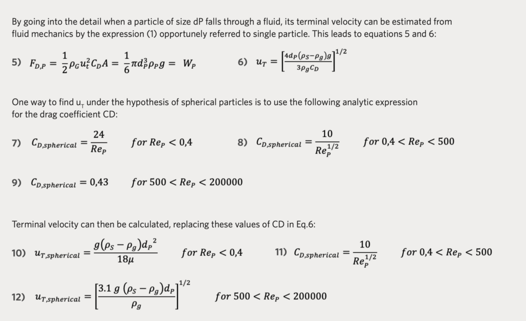
Fabio CravinoTechnology Director, Paul Wurth Italia S.p.A.
Articles by Fabio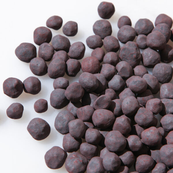
EDITOR'S NOTE
This article is the first of a two-part series on the subject of how pressure affects the operation of direct reduction processes. Part 1 focuses on the effect of pressure on particles entrainment, while Part 2 will describe the effects of pressure on iron oxide reduction kinetics.
INTRODUCTION
The operating costs (OPEX) of each industrial plant are essential in analysing a company’s economic performance and obviously, in having a successful business. This is generally true, especially in the competitive iron & steelmaking business. With focus on direct reduced iron (DRI) plants, many variables impact on the operating cost, such as raw materials and gas consumption, electricity consumption, and maintenance.
Yield, defined as the ratio between consumed iron oxide (IO) pellets and produced DRI, has a critical role in defining the plant OPEX performance. MIDREX® Direct Reduction Plants typically have a cut-point for the IO fines at 3mm, which contributes to an increase in the overall yield.
It should be noted that screening has a given efficiency and that some fines will be generated in the transport of oxide pellets from the screening station to the shaft furnace. As a result, some fines will find their way into the furnace. Any loss of such fines due to top gas entrainment will increase the overall material loss and consequently, worsen the overall yield.
One could be tempted to think that high pressure might be beneficial in reducing fines loss in the DRI plant’s top gas thanks to a reduction in top gas velocity. Also, it is sometimes said that high pressure DRI processes perform better than the MIDREX Process with respect to fines entrainment. But is this true?
The following article (Part 1 of a two-part series on the effects of system pressure on the operation of direct reduction processes) analyses the theory of fines entrainment to assess how pressure affects the entrainment phenomena and to compare the performance of the MIDREX Process and high pressure DRI processes with respect to fines loss via the top gas.
THEORY OF PARTICLE CARRY-OVER
If a gas passes at a low flow rate upward through a fixed bed of particles, where the particles are solidly packed, it simply flows through the void spaces between stationary particles, as shown in Figure 1.a.(1)
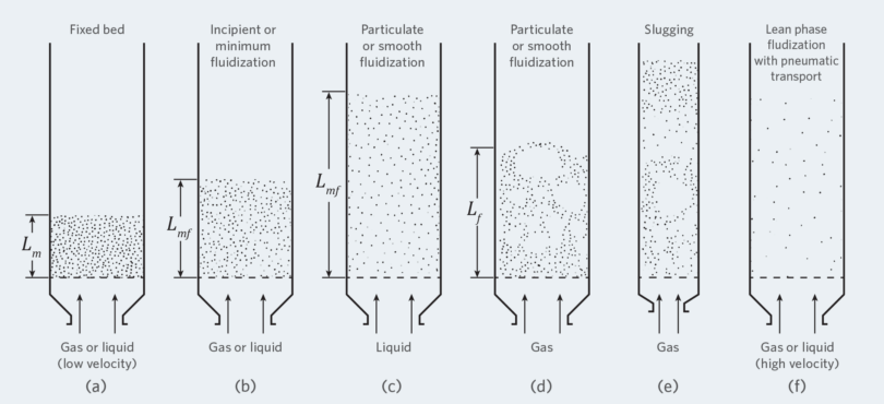
FIGURE 1.
Various forms of gas/solids contacting
If the fluid passes upward through a bed of particles with an increasing flow rate, the transition to an expanded bed occurs. In this condition, the particles move apart, a few vibrate and move in restricted regions.(1)
Finally, at even higher velocity, the fluidization, which is the condition where all the particles are just suspended by the upward-flowing gas, starts when the frictional force between particles and fluid counterbalances the weight of the particle bed:(1)
A bed that respects the above conditions is considered to be just fluidized and is referred to as a bed at minimum fluidization, as shown in Figure 1.b.(1)
The corresponding superficial gas velocity at incipient fluidization condition is known as gas velocity at minimum fluidizing conditions (umf) and can be found by re-arranging equation 1, as shown by Kunii & Levenspiel, 1969(1):
If εmf and/or φs are unkown, Wen and You expression, as stated in Kunii & Levenspiel, 1969(1), can be used to find umf.
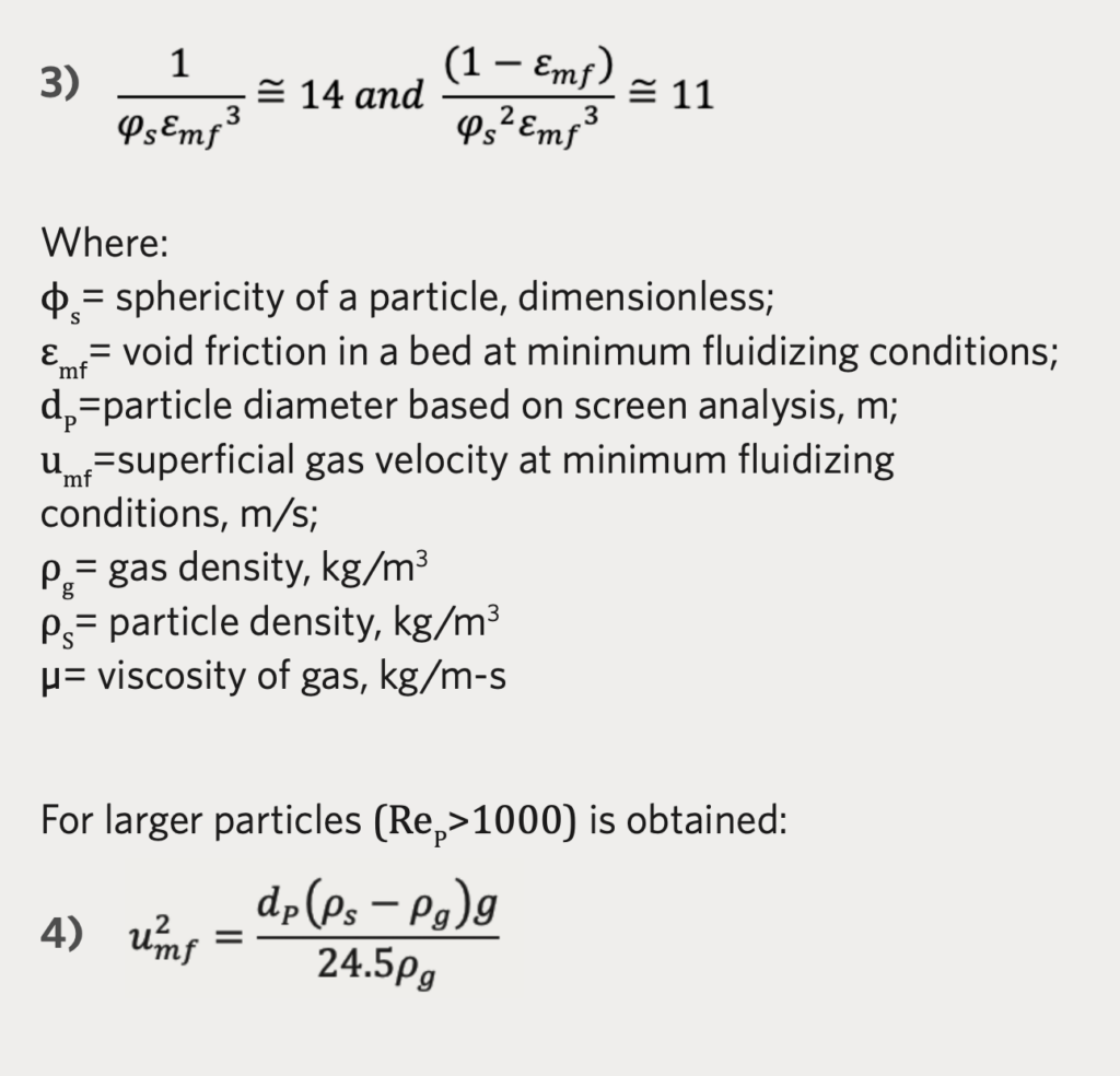
When gas velocity increases right above the minimum fluidization velocity (umf) expansion of the bed starts to occur smoothly, as shown in Figure 1.c. A bed in this condition is called a smoothly fluidized bed or liquid fluidized bed because expansion of the particles bed occurs progressively with small instabilities and low bubbling phenomena. When gas velocity increases well beyond the minimum fluidization, bubbling and channeling phenomena start to occur causing large instabilities. In these conditions the bed, which is called aggregative fluidized bed or bubbling fluidized bed, does not expand much beyond its volume at minimum fluidization, as shown in Figure 1.d.(1)
When gas flowrate increases enough to exceed the terminal velocity of the solid particles (u0>uT), the upper surface of the bed disappears and entrainment becomes appreciable. This state is represented in Figure 1.f and is named disperse-, dilute-, or lean-phase fluidized bed where, pneumatic transport of solids phenomena occurs.(1)
All the above can be summarized, as shown in Figure 2. As mentioned in the introduction, the process of interest is the particles entrainment, as this can affect plant OPEX. The effect of pressure on particles entrainment, as well as a comparison of MIDREX Process entrainment versus high-pressure DRI process entrainment (on furnace top gas) is given in following paragraphs.
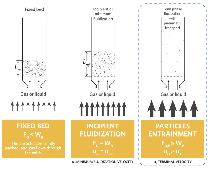
FIGURE 2.
Force balance on a single particle and Drag Force/ Gravitational Force relation for different beds (FD,P = Drag Force on single particle)(2)(1)
PARTICLE ENTRAINMENT: TERMINAL VELOCITY
For a particle to be carried-over from a bed, the local gas velocity needs to exceed the particle’s terminal velocity. This is defined as the lowest gas velocity that causes particles to start moving with the gas. By changing the reference system, the terminal velocity may be also defined as the speed at which a free-falling particle is no longer accelerating (see Figure 3). It is extremely important to remember that the terminal velocity is a property of the particle into its surrounding fluid environment! It is NOT a property of the moving fluid!
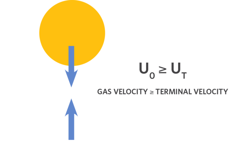
FIGURE 3.
Particle entrainment: Terminal velocity on a particle
In order to assess the effect of pressure on the terminal velocity, we assumed a typical MIDREX top gas composition and temperature, as well as typical IO pellet data (average size, sphericity, particle density, void fraction); we have calculated the resulting terminal velocity by varying pressure in the range between 2 bar- A and 7 bar-A . The result is shown in Figure 4.
Note: Figure 4 focuses on 2mm particles. As explained before, MIDREX Plants typically cut-point size is at 3 mm. Figure 5 shows three different pellets particle size analysis where the percentage of particles below 5 mm is around 1%. By considering only the particles below 2mm and the screening efficiency, this value can be further reduced.
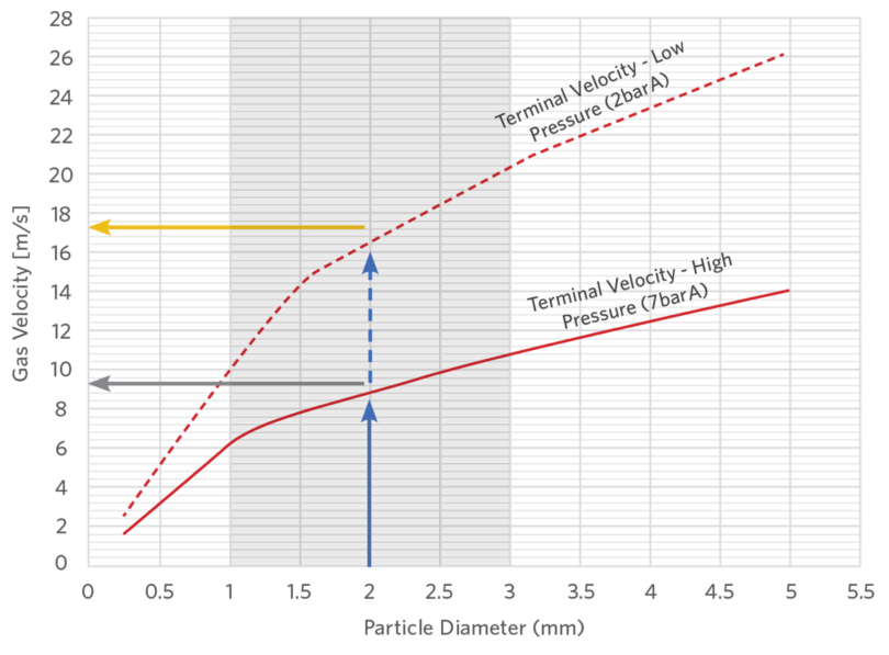
FIGURE 4.
Influence of pressure on Terminal Velocity at different particle diameters
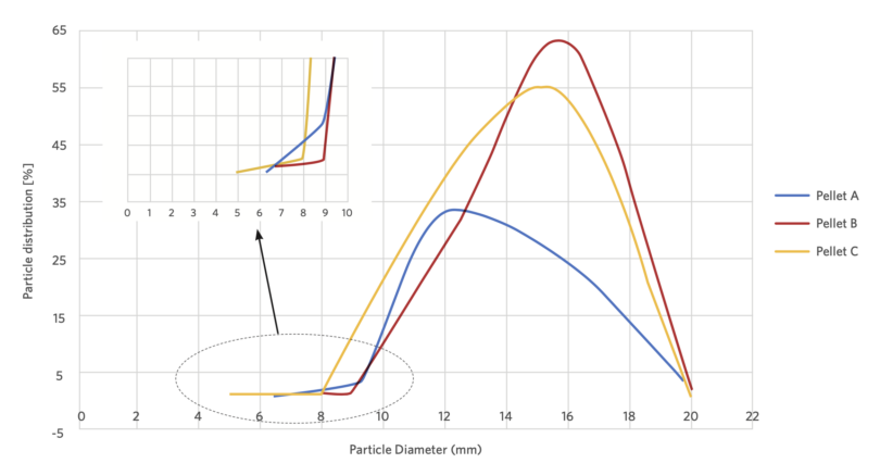
FIGURE 5.
Particle size analysis for three different pellets(3)
Therefore, 2mm represents a sensible value to evaluate entrainment threshold.
As can be seen, particle terminal velocity decreases with a rise in operating pressure and this decrease becomes more significant for larger particles. The main reason behind this is due to increase of gas density with increase of pressure.
Terminal velocity represents the threshold that operators do not want to overcome, as overcoming means entrainment. Obviously the higher the threshold the lower the margin towards entrainment.
If one considers a reactor filled exclusively with 2 mm diameter particles, entrainment starts with a gas velocity of approximately 9 m/s when the reactor is operated at high pressure. In the same reactor, when it is operated at lower pressure level, the same 2mm particles are entrained at much higher gas velocity, approximately 17 m/s. It is then true that high operating pressure implies lower gas velocities. But it is also true that entrainment starts at lower terminal velocity. The process with high pressure (and lower gas velocity) must be compared with a much more stringent limitation (lower terminal velocity) as gas becomes denser.
Another important fact to be considered when comparing the entrainment of the MIDREX Process and the high pressure process is that they are characterized by different furnace diameters, different specific flowrates, and different gas compositions and temperatures. If we imagine two plants (one MIDREX, one using the high pressure process) with the same production level, the MIDREX Plant is characterized by larger furnace diameter, lower specific flowrates, and lower gas temperatures. This means that the reduction of gas velocity one might expect by increasing pressure level is actually much lower in the high pressure process due to reduction of furnace free section and increase of specific flow-rate.
Therefore, if we aim to compare the entrainment of the two processes, a comparison should be done by incorporating all involved variables (by keeping same production level).
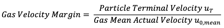
It is of particular interest to compare the two processes by making use of the following ratio:
Gas velocity margin > 1 means that there is not carry-over of particles. The threshold for 11 carry-over is at gas velocity margin = 1, so it is of 10 interest to operate a plant well above 1.
By considering the actual top gas composition, temperature, specific flowrate, and furnace diameter for both MIDREX and the high pressure process, the following plot has been realized (see Figure 6).
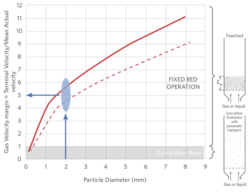
FIGURE 6.
Influence of pressure on particle carry-over at different particle diameters
There are two immediate outcomes from the analysis of Figure 6.
- Both processes have gas velocity margin well above 1 for particles with diameter bigger than or equal to 2mm, which means that carry-over phenomena could be widely averted.
- By looking closer to the largest particle that the two processes can entrain, it is noted that there are not significant differences for an industrial application (see Figure 7):
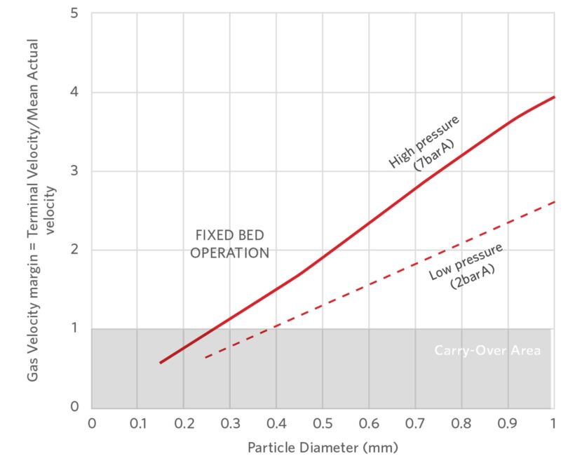
FIGURE 7.
Visualization of the largest particles that the two processes can entrain – negligible difference for an industrial application
Previous point number 1; i.e., the theoretical statement that MIDREX Process is designed with safe gas velocity margins for 2mm particles, is confirmed by a particle size analysis carried out on sample collection at the process classifier of one commercially operated MIDREX DRI Plant (as per construction features of the plant, the largest entrained particles are collected at the process classifier). The experimental data confirm the theoretical calculation: the size analysis result is that more than 92% of the particles of the sample are below 2mm in diameter, as confirmation of the above chart. Same values are confirmed by the article published by Lohmeiere et al.(4). Nevertheless, a small fraction above 2mm is found to be entrained by the top gas. What is the reason behind this slight deviation between theoretical and experimental results?
We must remember that the theoretical analysis has been done considering a perfect, uniform gas distribution, considering the average gas velocity. In reality, gas velocities may be higher than the average superficial gas velocity due to inhomogeneous material distribution inside the furnace. If the material is charged inside the vessel in a non-homogeneous way, velocity peaks may occur. In the presence of velocity peaks, the particles entrained are larger than the ones theoretically entrained when considering the average velocity.
Figure 8 shows how the material charging system can qualitatively affect material distribution inside the furnace and gas velocity peaks formation.
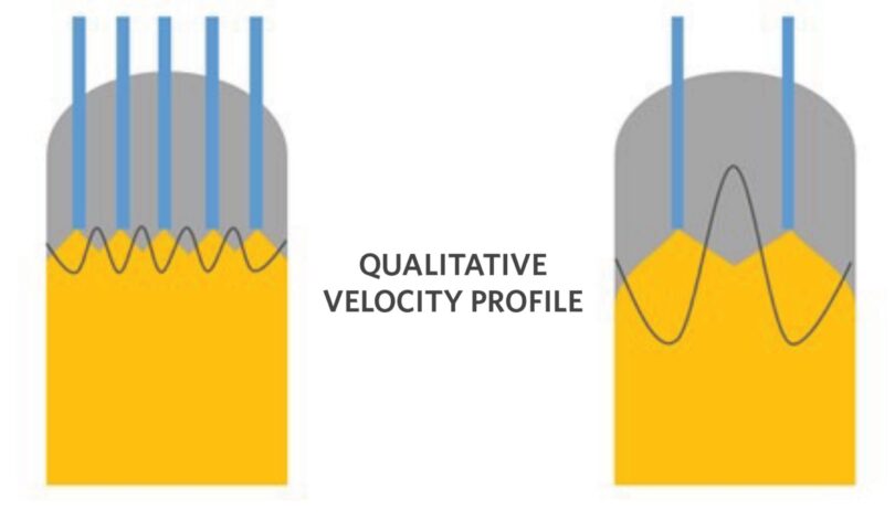
FIGURE 8.
Material charging system influence on gas velocity profile (MIDREX left, high pressure process right).
MIDREX Shaft Furnaces, as explained in following paragraph, are characterized by an IO pellets charging system shown in the left side of Figure 8: material is homogeneously distributed inside the furnace and velocity peaks are therefore limited.
On the other side, the high pressure process uses mechanical sealing for pressurization/depressurization from atmosphere (see following paragraph), with a lower number of charging points.
The following conclusion can be reached:
- MIDREX Process has limited deviation from ideal homogeneous gas distribution; velocity peaks are limited, and the largest entrained particle will be similar to the one calculated theoretically.
- High pressure process is further to the ideal gas distribution. There are stronger velocity peaks, and particles entrained will be significantly larger than the ones theoretically calculated.
FINES GENERATION AT FURNACE CHARGING
As we have seen in the previous discussion, the two processes have comparable carry-over potential. Therefore, the key factor for fines losses will be fines generation, which might sound obvious but non-generated fines will not be entrained!
Besides the intrinsic characteristics of the charged material, furnace charging and sealing systems play a major role on fines generation (Figure 9).
MIDREX Shaft Furnaces are characterized by IO pellets charging system where seal legs and feed legs connect the furnace charge hopper to the reduction furnace. These are designed to prevent segregation of material and to uniformly distribute the incoming material in the reduction furnace. Each feed leg receives an equal quantity of oxide and the multiple charging points guarantee even bed distribution. This feeding system has been proven extremely effective in ensuring uniform particle size distribution, uniform stock line profile, and in the end, an uninterrupted and gentle material descent from top to bottom.(5)
On the contrary, high pressure charging systems manage high operating pressure through use of mechanical sealing for decoupling from atmosphere. The high pressure lock hoppers lead unavoidably to a discontinuous material charge with uneven bed distribution because of the limited number of charging points. Additionally, because of the nature of the high pressure charging system, particles are subject to falls and interruptions that generate fines production.
Therefore, the MIDREX Process and its equipment guarantee a more uniform stock-line profile (lower velocity peaks, as explained before) and less intrinsic fines generation compared to the high pressure process.
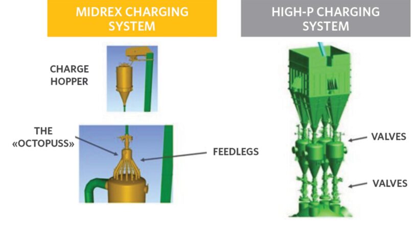
FIGURE 9.
3D view of a comparison between MIDREX charging system and high pressure charging system
REAL CUSTOMER EXPERIENCE
A comparison between MIDREX Plants and high pressure process plants, from real customer experience, is shown in Table 1. One overall fines comparison has been carried-out on the clarifier sludge annual quantity from two plants operated by the same owner/company, with the same iron oxide quality, one MIDREX, one the high pressure process.
The results of the comparison leads to a 28% higher clarifier sludge quantity in the high pressure plant.
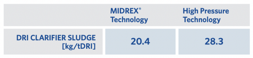
TABLE 1.
DRI clarifier sludge data from two comparable plants (MIDREX vs high pressure)
CONCLUSION
This paper treated the theory of particles entrainment, as well as discussed the different variables characterizing the MIDREX and the high pressure process with respect to particles entrainment.
Main takeaways:
- Increasing pressure reduces gas velocity but increases gas density. The apparent benefit of pressure rise is balanced as the terminal velocity lowers (or the drag force rises) due to gas density increase.
- The reduction of gas velocity, thanks to higher pressure, is offset in high-pressure process plants by:
- Lower furnace section
- Higher specific gas flow-rate
- Higher temperatures
- MIDREX Technology is characterized by more favourable solids distribution in the furnace: uniform stock-line profile and lower chance of velocity peaks.
The MIDREX Process and the high pressure process have comparable entrainment capacity. However, MIDREX Technology has a much lower tendency to generate fines in the furnace charging section. By having the same entrainment capacity but a significant difference in fines generation at charging, the high pressure process is expected to lose more fines in the furnace top gas. This is confirmed by the plant data shown in Table 1.
References:
- Kunii, Daizo and Levenspiel , Octave . Fluidization Engineering. [ed.] Butterworth—Heinemann. 1969.
- Neutrium. [Online] 9 July 2013. [Cited: 6 May 2022.] https://neutrium.net/unit-operations/terminal-velocity-ofparticles-for-gravity-separation/.
- Poveromo, Dr. Joseph J. [Online] [Cited: 2022 July 2022.] https://docplayer.net/29858192-Dr-grade-pellet-qualitysupply-and-prices.html
- Investigation into the Hot Briquetting of Fine-Grained Residual Materials from Iron and Steel Production. Lohmeier, Laura, Wollenberg, Ralf and Schröder, HansWerner. Weinheim : s.n., 2020.
- REMODIFICATION IN THE OXIDE FEED SYSTEM FOR MIDREX DIRECT REDUCTION . Olayebi, Oluwafemi O. Department of Chemical Engineering, Federal University of Petroleum Resources, Effurun, Delta State, Nigeria. : s.n., 2014, Vol. Global Journal of Engineering Science and Research Management.
- Introduction to Fluidization. COCCO, RAYMOND, KNOWLTON, TED and KARRI, S. B. REDDY . s.l. : American Institute of Chemical Engineers (AlChE), 2014.
Related Reading
 Mar 25, 2026
 Dec 05, 2025