
Getting the Most From Direct Reduced Iron – Operational Results of MIDREX® Hot Transport-Hot Charging
Brian VoelkerChief, Proprietary Equipment
Articles by Brian
Sean BoyleVice President - Commercial
Articles by Sean
INTRODUCTION
The introduction of the hot discharge furnace for producing hot briquetted iron (HBI) not only made it safer and easier to transport direct reduced iron (DRI) as a merchant product, it led to the development of methods for transporting and charging hot DRI (HDRI) into an electric arc furnace (EAF) to take advantage of the sensible heat in the HDRI. The result is increased productivity and yield, as well as reducing the need to inject carbon to balance the EAF heat, thus lowering carbon dioxide (CO2) emissions.
By using one of three hot transport systems – hot transport vessels (HTV), hot transport conveyor (HTC), and HOTLINK® – HDRI can be charged to an EAF at up to 650° C.
Key to the success of its hot transport/hot charging (HT/HC) systems is the experience Midrex gained from designing the hot discharge furnace for Sabah Gas Industries (now Antara Steel Mills) in 1984. The MIDREX® Hot Discharge Furnace has proven to be a keystone technological development that makes possible the innovative combination plant design which gives operators the ability to respond quickly and effectively to changing market conditions.
HT/HC of DRI is technically challenging and requires close and complete coordination between the DRI plant and the steel mill. Special handling is required for HDRI to protect it from exposure to air and prevent reoxidation and loss of temperature from the time it is discharged from the reduction furnace to when it is charged into the EAF.
This article discusses the benefits and challenges of transporting HDRI from the direct reduction plant to the melt shop and the solutions available from Midrex.
THE ORIGIN OF HDRI
When the hot discharge furnace was designed for the first MIDREX HBI Plant, which was started up in 1984, the stage was set for the addition of HDRI as another product option. The MIDREX Shaft Furnace operates at a relatively low pressure (≤1 barg), which simplifies the charging and discharging systems. The most important innovations embodied in the hot discharge furnace design are how it barometrically seals while discharging HDRI and how uniform material flow is maintained. Two dynamic seals accomplish the same task that would require more than 20 mechanical valves and five lock hoppers if the furnace were designed to operate at a pressure of 5-6 barg. The lower pressure operation of the reduction furnace and the bottom seal leg/product discharge chamber (PDC) arrangement are of particular importance in a MIDREX Combination Plant to achieve true simultaneous discharge of cold DRI (CDRI) and HDRI while maintaining consistent chemistry throughout the material bed and uniform material flow in the furnace.
BENEFITS OF HOT CHARGING DRI
Hot charging DRI is a proven method for effectively lowering the cost per ton liquid steel (tls). There are two primary benefits of hot charging DRI to an EAF:
- Increased furnace productivity and lower energy costs for melting.
- Reduction in the amount of pollutants per ton liquid steel.
The productivity boost results from shorter tap-to-tap times, which are made possible by the sensible heat retained in the HDRI which reduces the amount of electric energy and/or carbon injection needed to achieve melting temperature of the DRI.
For example, in Table I we have estimated that productivity can be increased from 4-17% when charging HDRI vs. CDRI in an EAF and the energy savings, which can range from 28-105 kWh/tls, based on actual HDRI chemistry.
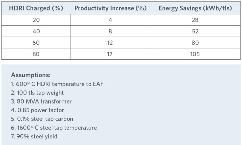
TABLE I.
Estimated Operating Results Charging HDRI in EAF
Hot charging DRI also reduces the total amount of pollutants produced per ton of liquid steel. By utilizing the sensible heat contained in HDRI rather than releasing it to the atmosphere, hot charging DRI provides environmental benefits in three ways:
- Shorter time spent melting the DRI lowers EAF emissions
- Lower electricity demand from the utility reduces power plant emissions per ton of liquid steel
- Reduced amount of carbon injected for heating and melting results in less CO2 emissions
Actual operating results achieved by Tosyali Algérie show a >27% reduction in power required/mt of steel, a >28% improvement in tap-to-tap time and a subsequent 30% reduction in power on time, resulting in >41% more heats/day when charging 100% HDRI vs. 100% CDRI (see Table II).
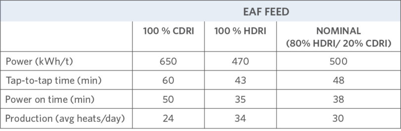
TABLE II.
Results of Charging HDRI vs. CDRI (reported by Tosyali Algérie)
Midrex and its Construction Licensees have supplied 13 hot discharge plants equipped with hot transport since 1990: seven producing HDRI/CDRI, six producing HDRI/HBI. This represents nearly 20.0 million metric tons of installed capacity (see Table III).
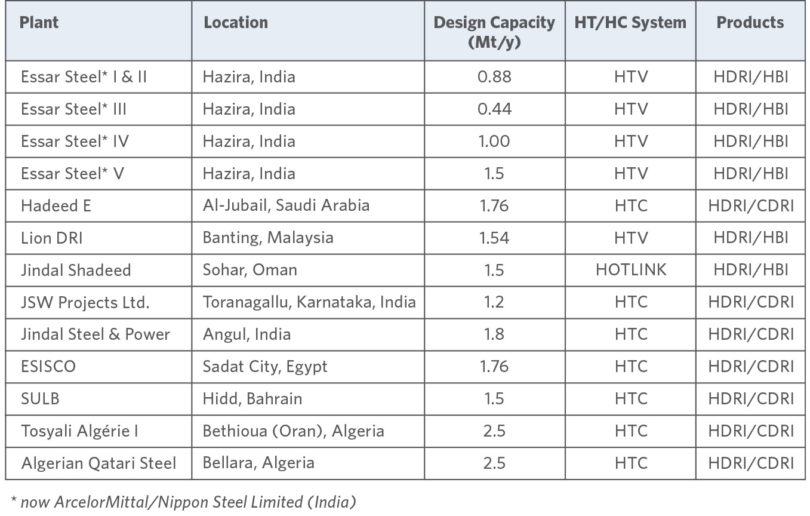
TABLE III.
MIDREX Plants with Multi-Product Capability
METHODS AND CRITERIA FOR HOT TRANSPORT/HOT CHARGING DRI
In order to reap the operating benefits from hot charging DRI, it is essential to keep the HDRI at a consistently high temperature regardless of the distance between the MIDREX Plant and the EAF melt shop. Midrex offers three systems for plants equipped with a hot discharge reduction furnace that minimize temperature loss and prevent loss of metallization due to reoxidation of the HDRI during transport:
- HOTLINK
- Hot Transport Conveyor (HTC)
- Hot Transport Vessel (HTV)
Important factors to consider are whether the installation is greenfield or retrofit, installation cost, operating cost, generation of fines, temperature loss, carbon loss, ease of operation, and reliability. The system for transporting HDRI is mainly chosen based on distance to the melt shop in accordance with Table IV.
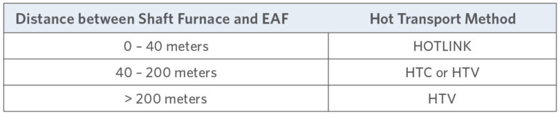
TABLE IV.
Suggested Distances for Hot Transport Systems
Figure 1 shows a breakdown of the various methods of hot transporting/hot charging used by MIDREX Plant from 2011 through 2021.
There are three separate tasks that must be accomplished within the flowsheet in all transport systems:
- Discharge the DR furnace at a controlled continuous rate.
- Transport the HDRI to the melt shop.
- Feed the HDRI to the EAF at a controlled rate at the appropriate time that the EAF requires it in the heat cycle.
Because melt shops operate with frequent maintenance shutdowns and DR furnaces only shut down once every 1.5 years, it is necessary to have a second avenue for the HDRI to go when the EAF is between campaigns. What to do with the DR furnace production during EAF downtime is dependent on market strategies of the producer.
There are three options for the HDRI when the melt shop is not in operation:
- Cooling and storing the cooled DRI for later use
- Hot briquetting and either selling the briquettes or storing for later use
- Transporting the HDRI to another EAF
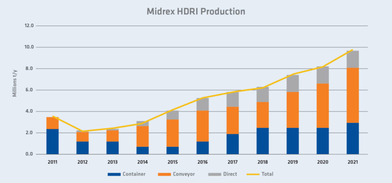
FIGURE 1.
HDRI Production by MIDREX Plants 2011-2021
PROCESS DESCRIPTION OF HOT TRANSPORT SYSTEMS
HOTLINK
HOTLINK delivers HDRI to an adjacent EAF at up to 700°C directly from the reduction furnace positioned just outside and above the exterior wall of the EAF melt shop (see Figure 2). HDRI is discharged into a surge bin and then fed by gravity directly to the EAF with minimum heat loss. Low-velocity, gravity transport keeps physical degradation of the HDRI to a minimum and the sealed design of the HOTLINK system ensures there is no reoxidation of the HDRI. HOTLINK is available with options to produce HBI or CDRI when the EAF is offline without the need to stop DRI production.
The first HOTLINK plant is in Oman and is owned and operated by Jindal Shadeed and has produced nearly 10 million tons of HDRI since 2012.
A second-generation HOTLINK Plant (HOTLINK 2G) was built for ESISCO in Egypt. In HOTLINK 2G, the HDRI storage bin is direct coupled with the PDC and located in the furnace tower. In addition, a short, horizontal hot transport conveyor is used to convey HDRI from the storage bin to the EAF. HOTLINK 2G allows the furnace tower to be lowered by 12 meters.
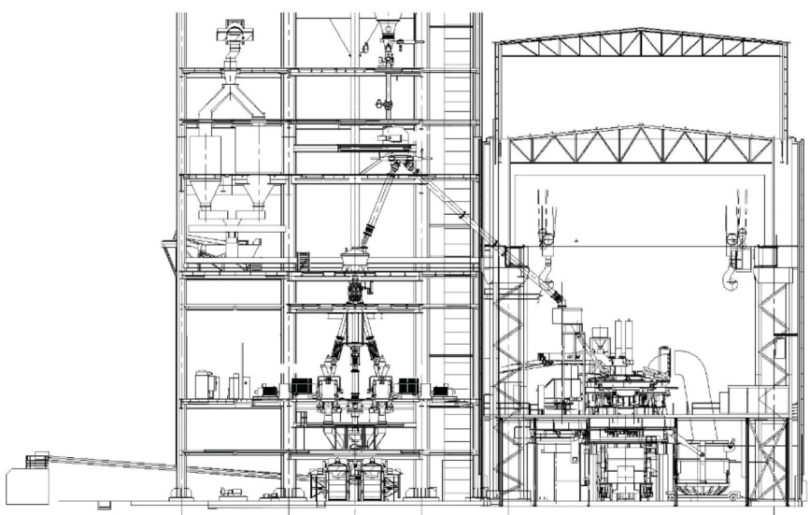
FIGURE 2.
Schematic of HOTLINK-EAF Arrangement
Hot Transport Conveyor (HTC)
HTCs are specially designed, covered, and insulated bucket-type conveyors to transport HDRI for distances up to 200 meters. The HTC system continuously transports HDRI from the discharge of the MIDREX Shaft Furnace via an inclined bucket conveyor into storage bins located directly above the EAF. This allows the MIDREX Shaft Furnace to discharge HDRI at a significantly lower elevation than the EAF. HTCs have lower energy and maintenance costs and generate less fines than pneumatic transport systems.
HTC systems are operating at Hadeed in Saudi Arabia (shown in Figure 3), Jindal Steel & Power Limited in India, JSW in India, SULB in Bahrain, and Tosyali Algérie I and AQS in Algeria.
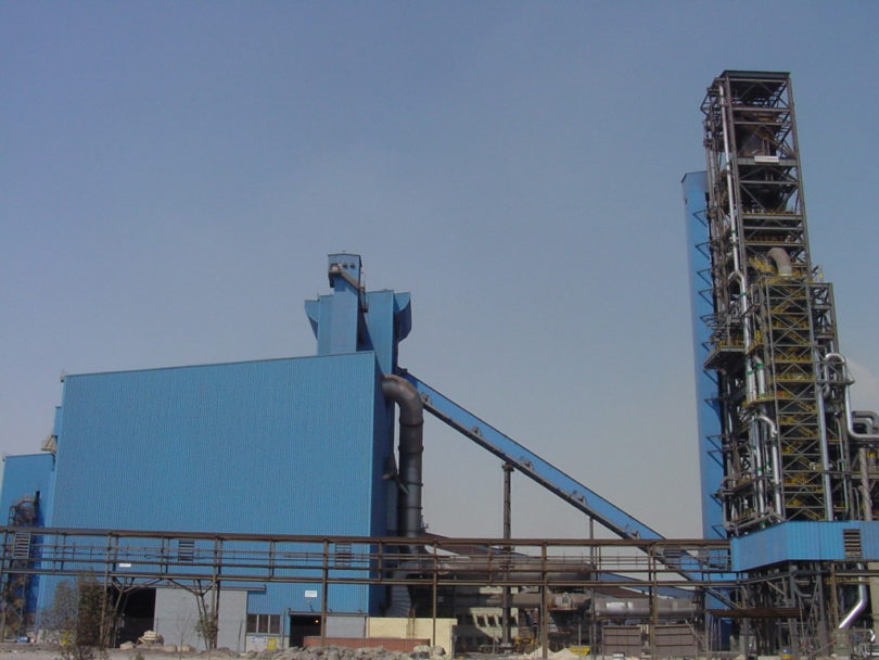
FIGURE 3.
HTC Between MIDREX Plant (Hadeed E) & Melt Shop
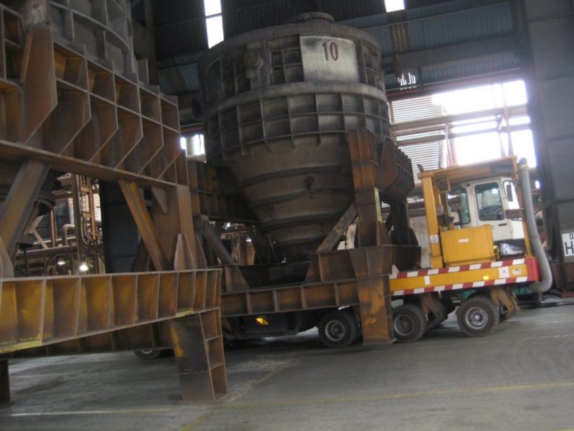
Hot Transport Vessel (HTV)
HTVs are refractory-lined containers typically with a capacity of 45-90 metric tons. HDRI exits the MIDREX Shaft Furnace and is discharged into these containers, which are then transported by truck or rail to the steel mill and placed in an automated overhead receiving station by the scrap charging crane. From here, the HDRI can be discharged directly into the EAF. A telescoping device seals the opening of the HTV to the discharge feeder and initiates the HTV isolation valve operating sequence. HTVs are ideal when the distance from DRI plant to EAF is greater than 100 meters. They maintain the HDRI under inert conditions throughout the entire fill–transport–discharge cycle to minimize loss of metallization and retain maximum temperature.
The HTV method has been used in India since 1998 by ArcelorMittal/Nippon Steel India (formerly Essar Steel) and was operated by the Lion Group in Malaysia from 2007 until the Lion DRI plant was shuttered in 2017.
OPERATION DETAILS AND RESULTS
Direct Charging by HOTLINK (Original HOTLINK design)
Direct charging is perhaps the simplest of the HT/HC systems. After the material is discharged from the furnace and depressurized, the HDRI is alternately fed into two EAF feed bins to adapt the continuous DR furnace discharge to the batch feeding that an EAF requires. The HDRI is fed at a controlled rate to a feed leg that feeds the EAF directly using only gravity as the means of transport.
Equipment Description at Jindal Shadeed (downstream of PDC)
- HDRI bin feeders – Vertical screw feeders to meter DR furnace output and fill HDRI surge bins.
- HDRI feed bins – to provide surge between DR furnace continuous operation and EAF batch operation. On load cells for loss-in-weight feed control
- HDRI feeder to EAF – Rotary feeder to control feed rate to the EAF
Results of operation
In January 2016, the steel mill reported EAF electricity consumption of ~529 kWh/tls while using ~75% HDRI, ~25% HBI, and scrap. The MIDREX Shaft Furnace was operated using 85% blast furnace-grade pellets with higher gangue content than DR-grade pellets. HDRI carbon content was 1.8% and metallization was 93-94%. HDRI was discharged at a temperature of ~650° C and was charged into the EAF at a temperature of 622° C.
Advantages
- Minimal moving parts
- Lowest power consumption
- Easiest logistics
- Low manpower requirements
- Lowest inert gas usage
- Lowest temperature (and carbon) loss
Disadvantages
- Taller DR furnace tower
- Retrofited to existing melt shop
- Long chute to EAF could result in HDRI breakage
Process description (HOTLINK 2G)
HOTLINK 2G was developed to shorten the height of the DR furnace tower, and is installed at ESISCO in Egypt. In HOTLINK 2G, HDRI is discharged and held in one feed bin before it is transported horizontally by conveyor to the melt shop. By using a short horizontal conveyor and one surge bin, 12 meters in the height of the DR furnace tower were eliminated.
A disadvantage of this flowsheet is that it is not possible to know the precise discharge rate (by weight) of the DR furnace because the HDRI feed bin will be emptying and filling at the same time. Also, there is a lag between discharge of the HDRI bin and the feed of the HDRI to the EAF, which forces the melt shop to plan ahead for changes to feed rate.
Equipment description (downstream of PDC)
- HDRI bin feeders – Only PDC wiper bar to meter DR furnace output and to control feed to the single HDRI Feed Bin.
- HDRI feed bin – to provide surge between DR furnace continuous operation and EAF batch operation. On load cells to determine HDRI level in the bin.
- HDRI feeder to EAF – Rotary feeder operating in a volumetric basis to control feedrate to the EAF
Results of operation
We have limited experience with HOTLINK 2G because ESISCO has been able to run at full capacity only a short time due to commercial reasons.
Advantages
- Shorter furnace tower than for First Generation HOTLINK
- Lowest power consumption
- Low manpower requirements
- Low inert gas usage
- Low temperature loss
- Low number of drops and low heights of dropping HDRI – less breakage
Disadvantages
- Requires more advanced planning and foresight by melt shop
- Allows only intermittent feedback of DR furnace discharge rate
- Provides only volumetric control of EAF feed (not controlled by loss-in-weight)
- Possibility of exposing HDRI to air at conveyor transport points with potential for increased temperature and carbon loss
Hot Transport Conveyor (HTC)
Process description
After depressurizing the PDC, the HDRI is metered into the conveyor by a rotary feeder. The rotary feeder both meters volumetrically and distributes the HDRI across the width of the bucket apron conveyor. Transportation to the melt shop is by metallic apron conveyor which can be inclined up to 34°. The width of the buckets and speed of the conveyor are based on the rated capacity of the conveyor. The maximum lift, capacity, and length of one conveyor is limited by the strength of the chains. The entire conveyor is enclosed and an inert gas is injected along the length to minimize metallization and carbon loss.
At the discharge of the conveyor, the HDRI is diverted to fill one of two HDRI feed bins before discharging to the EAF. The bins act as a surge capacity with loss in weight measurement and are sized so each bin will hold at least enough HDRI for one heat of the EAF. The bins are mounted on load cells to indicate the weight of HDRI in the bin. During operation, one bin is filled while the other is being emptied.
The HDRI is discharged by a rotary feeder, which discharges to a chute that goes into the roof of the EAF. The EAF operator controls the rotary feeder rate according to the heat charging cycle.
Results of operation
The operational results shown in Table V have been reported by an operating MIDREX Plant with a hot transport conveyor system.
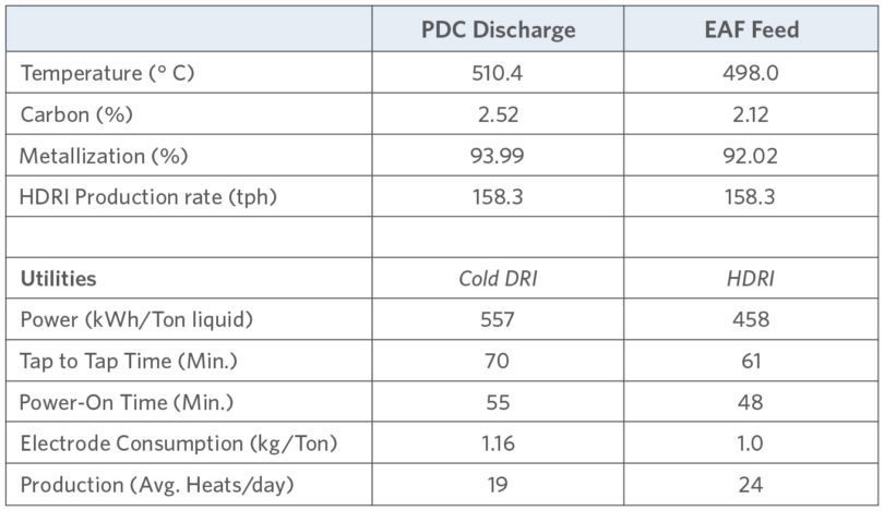
TABLE V.
HTC Operational Results
Benefits
- 17.78% power savings
- 12.86% tap-to-tap time savings
- 20% productivity increase by reducing tap-to-tap time
- Reduced emissions by retaining sensible heat in HDRI, which 1) lowers electricity demand (reduced power plant emissions per ton of steel), and 2) reduces energy requirement in EAF (less carbon injection, which reduces amount of CO2 emissions)
- 20 kWh/tls electricity savings for every 100° C increase in HDRI temperature (at least 120 kWh savings when charging at least 600° C HDRI)
- 0.5-0.6 kg/tls electrode savings
- 1.8-2.0 kg/tls refractory savings
SULB, which is equipped with an HTC system, set an annual production record in 2018 and a new monthly production record in 2019, averaging 215 t/h. Over 1.0 million tons of HDRI were sent directly to the steel mill in 2019, while more than 60% of the balance was exported by ship as CDRI. HDRI temperature (at the PDC) exceeded 650° C, metallization was 94.9%, and carbon was 2.28%.
Advantages
- Able to feed multiple EAFs as long as they are close enough to the DR furnace tower
- Precise control of HDRI feed to EAF
Disadvantages
- Requires careful coordination with melt shop for placement of bins and conveyor support structure
- Conveyors require maintenance, however long term have proven to be reliable.
- Requires a higher quantity and careful application of seal gas to maintain HDRI metallization and carbon.
Hot Transport Vessel (HTV)
The capacity of HTVs is determined by several factors including head room of the roadway to the melt shop, discharge capacity of the DR furnace, heat size of the EAF, and manageable size of the vehicle (truck or rail). In the case of the Lion plant in Malaysia, the transportation of the HTVs from the loading point at the DR furnace is via rail-based shuttle cars to the buffer transport station. From there, the HTVs are loaded by bridge crane onto rubber-tired trucks that transport the HDRI to the changing bays of the melt shops. Once at the EAF charging bay, the HTVs are lifted from the transport trucks by EAF charging cranes to an HDRI charging stand that is located above each EAF. After positioning the HTV in the charging stand, the vessel is connected to the discharge pipe and the hot conveying system of the charging stand. HDRI is charged via a hot conveyor into the EAF at feed rates according to the actual melting process requirements of the EAF. For emergency situations, HDRI can be discharged via a chute to the ground level.
Equipment descriptions
- Loading Equipment – After exiting the PDC, the HDRI is fed alternately by one of three vertical screw feeders into HTVs. The HTVs are then loaded onto the vehicles for transport to the melt shop.
- Transport Equipment – The vehicles to transport the vessels to the melt shop can be either rubber-tired carriers or flatbed railcars. The method of transport depends on the plant layout. Rubber-tired vehicles are much more versatile with regards to timing the vessels and routing; however, they require more manpower and maintenance to operate. Lion has 15 fabricated containers and three trucks to feed both melt shops.
- Unloading Equipment – Vessels are unloaded from the vehicles by the melt shop crane. Alternately, special vehicles can be used to unload the vessels without assistance from the crane. These vehicles can have either hydraulic beds that lower the vessel (along with a mobile stand) or arms that lift the vessels off the vehicle and place them in a stationary stand. The melt shop crane then places the vessels in a charging stand to be discharged to the EAF by feeder/conveyor (the charging stand concept was patented by Midrex in 2010).
Results of operation
Melt shop benefits:
- Shorter tap-to-tap times (increased productivity and yield)
- Reduced by 3 minutes (45-ton HTV)
- Reduced by more than 5 minutes (90-ton HTV)
Electricity and electrode savings
- Heats using one 90-ton HTV charge of HDRI saved average of 60 kWh/t liquid steel (equates to 120 kWh/t savings when using 100% HDRI charge)
- Electrode savings over 8-month period averaged 0.3 kg/t liquid steel
Decreased moisture in EAF charge
- No moisture in HDRI (0.75% moisture in HBI from water-quenching)
- HDRI has 1.0-1.5% higher metallization
Challenges
- Essar Steel (now AM/NS India) initially had problems with HDRI plugging at the discharge of the vessels. This was resolved by making the outlets larger and keeping an inert atmosphere in the vessel during long wait times.
- Lion reported breaking the chassis of both transporters due to road conditions and the weight the trucks were carrying.
- Lion reported problems with plugging of the feed pipes dust collection to the vessels and rupturing of the telescoping chute after a short time
- Lion reported they were experiencing about 50° C temperature loss between the PDC and the charge hopper of the EAF. Further continuous monitoring of the vessels in transit demonstrated that the closed vessels only experienced a 2° C temperature loss per hour, which proved that the primary temperature losses were occurring during the loading and unloading of the vessels.
Advantages
- Easiest method to implement as a retrofit
- Able to feed multiple EAFs even if they are a long distance apart
- DR plant can be located relatively far from the melt shop
Disadvantages
- Large capital cost because of the number of HTVs required
- Large manpower requirement
- Ties up melt shop building crane for loading containers into charging stand
- Logistically challenging
CONCLUSION
Three distinctive operations are involved in producing and using HDRI, each of which poses technical challenges and requires specific conceptualization, engineering, and implementation efforts:
- Hot discharging DRI from the reduction furnace
- Transport the HDRI to the melt shop
- Charging HDRI into the EAF
Hot transporting/charging DRI is most economically realized when the decision is made in advance of the design and construction of a “greenfield” plant. However, the flexibility of the MIDREX Process allows for modifying an existing HBI plant equipped with a hot discharge reduction furnace or for retrofitting an older plant currently producing CDRI. Careful evaluation of the plant layout should be considered when proposing a method of hot transport. It is not a simple formula involving only distance to the melt shop, although the distance is one of the major factors.
HOTLINK
This system involves putting the HDRI bins in the DR furnace tower and feeding the melt shop directly via a feed leg. It is the simplest and lowest operating cost method. It provides the advantages of a precise weight controlled EAF feed, absolutely no possibility of exposure to atmosphere before it enters the EAF, and no mechanical transport parts to maintain. The biggest disadvantages are that it raises the DR furnace height significantly and careful coordination with the melt shop supplier during the layout of the integrated plant is required.
HOTLINK 2G loses a few of the advantages mentioned above because the feed to the EAF and the discharge of the DR furnace is volumetrically controlled, which is less precise. Additionally, there is also the possibility of exposure to oxygen at the transport point to the conveyor and the mechanical conveyor requires maintenance and control. However, it does lower the DR furnace tower due to the horizontal transport of the HDRI, but close coordination with the melt shop supplier is still necessary for support and routing of the conveyor through a congested area of the melt shop.
Hot Transport Conveyor (HTC)
To date, HTCs have been the most popular option for a greenfield site. The system has been well proven and improvements in sealing the conveyor to prevent metallization and carbon loss ensure that this will continue to be the trend. It has the advantage of lowering the DR furnace tower, as well as providing a reliable and controllable HDRI feed rate to the EAF. Consideration of the melt shop layout is important up front, as well as the operating parameters of the EAF. HDRI bins need to be sized to accommodate the heat size of the EAF and space needs to be reserved in the melt shop for the bins, as well as for a good route to the top of the HDRI bins for the conveyor. Maximum inclination angle and length of the conveyor must be approved on a case-by-case basis by the conveyor supplier.
Hot Transport Vessel (HTV)
If a melt shop exists on the site before the DR furnace site is planned and there is not a good route for an HTC, using HTVs is often the only choice. In some cases, HTVs can be the best choice for new melt shops, such as if the client will be charging multiple small furnaces with HDRI. HTVs should not be considered if there is a possibility of another viable method because it is the most capital intensive and logistically challenging of the Midrex HT/HC systems.
For long term operation, lowest OPEX will tend to govern, so the best option will depend on temperature of HDRI into the EAF and overall plant availability. As a result, HOTLINK or HOTLINK 2G should prove to be more economical than the HTC or HTV options over the life of the plant.
Note: This article is based on a paper titled, “Operational Results of Hot Charging DRI” by Brian Voelker and Sean Boyle, which was presented at the AISTech 2022 Exposition & Conference in Pittsburgh, PA
References:
- Russ Bailey, Essar Steel, Ltd., “Benefits of Hot DRI Charge to the EAF,” Direct From Midrex 2Q2001, Midrex Technologies, Inc., Charlotte, NC, USA, pp 7-8.
- Todd Ames and John Kopfle, Midrex Technologies, Inc., “Heating Up the Bottom Line: The Economics of Hot DRI Charging,” Direct From Midrex 2Q2007, Midrex Technologies, Inc., Charlotte, NC, pp 7-9.
- Gary Metius and John Kopfle, Midrex Technologies, Inc., “Hot Charging DRI for Productivity and Energy Benefits at Hadeed,” Direct From Midrex 2Q2009, Midrex Technologies, Inc., Charlotte, NC, USA, pp 8-11.
- Mohammad Siddiqui, SULB, “Introduction to the SULB DR Plant,” Midrex Operations Seminar, 12-16 October 2014, Munich, Germany.
- Frank Reddemann, Aumund Fōrdertechnik GmbH, and John Kopfle, Midrex Technologies, Inc., “Hot Transport Conveying of DRI for Energy and Productivity Benefits,” Direct From Midrex 1Q2009, Midrex Technologies, Inc., Charlotte, NC, pp 6-9.
- M. Hein, SVAI/MT Germany, and G. Peer, R. Beyer, SVAI/ MT Linz, “Looking at DRI for EAF Usage: The Correct Carbon Content?,” Direct From Midrex, 3Q2012, Midrex Technologies, Inc., Charlotte, NC, pp 11-15.
- Markus Abel, SVAI/MT GmbH, “SIMETALCIS EAF with HOT DRI – Worldwide Benchmark,” 12th Middle East Iron & Steel Conference, 14-16 December 2008, Dubai, UAE.
- Robert Klawonn and Glenn Hoffman, “Optimum Utilization of Hot DRI: An Innovative Approach to Integration with Steelmaking Processes,” AISTech 2005.
- Stephen Montague, Midrex Technologies, Inc., and Dr. Dieter Hausler, SMS Demag AG, “HOTLINKTM Hot Charging DRI for Lower Cost and Higher Productivity,” 57th Electric Furnace Conference, 14-16 November 1999, Pittsburgh, PA
- Todd Ames, Henry Gaines, and Chris Ravenscroft, Midrex Technologies, Inc., “Producing DRI in Bahrain: United Steel Company (SULB),” Direct From Midrex 3Q2015, Midrex Technologies, Inc., Charlotte, NC, pp 11-14
- Siddiqui, Mohammad R., Tosyali Algérie, “Direct Reduced Iron Technology – Tosyali Algerie, Largest DRI Plant in the World,” AIST Webinar, February 2021.
Related Reading
 Mar 25, 2026
 Dec 05, 2025