
Impact of Hydrogen DRI on EAF Steelmaking
Dr. Sara HornbyGlobal Strategic Solutions, Charlotte, N.C. USA
Articles by Dr.
Professor Geoff BrooksSwinburne University of Technology, Melbourne, Victoria, Australia
Articles by Professor
INTRODUCTION
The world steel industry constitutes 8% of the overall energy demand whilst contributing 7% of the total carbon dioxide (CO2) generated by humanity (2.6 GTonne [GTe] CO2 2020; 2.8 GTe CO2 2015) [(1, 2), Figure 1]. The great majority of this CO2 generation is due to coal, constituting 75% of the energy used in the steel industry, predominantly in the ironmaking process, where carbon is used chemically to reduce iron oxide and provide fuel for the process. In the case of the Iron Blast Furnace, carbon (in the form of coke) also plays a vital role by providing structure and mechanical support to the bed of materials in the reactor shaft.
Figure 1 summarizes the generation and required CO2 reductions, the anticipated increase in steel demand, and the required change in carbon intensity between 2015 and 2050(3). The massive potential generation of CO2 from industrial processes and transportation is the motivation behind the desire to decarburize and become a Hydrogen Economy (using H2 as a fuel source). This, of course, assumes cheaper and ‘greener’ methods of H2 production become reality.
In the case of shaft furnace-based direct reduction (DR) processes, such as MIDREX®, a reducing gas mixture of carbon monoxide (CO) and H2 is produced from the decomposition of natural gas. Carbon does not play a key role in the process; however, increasing the H2-to-CO ratio does have a significant effect on the process heat balance. In fact, there is substantial evidence that carbon can be removed from the process and replaced by H2, as was discussed in the first quarter 2020 issue of Direct from Midrex (4).
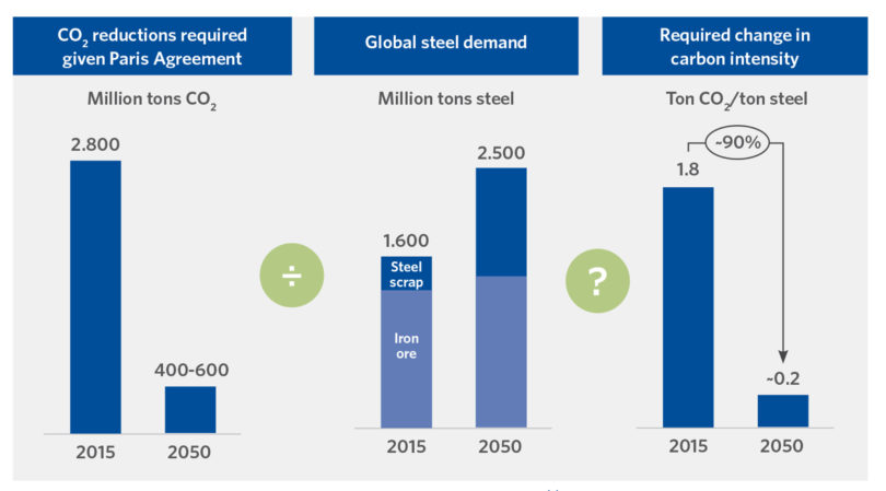
FIGURE 1.
Required Change in Carbon Intensity 2015 to 2050 (3)
WHAT IS MEANT BY GREY, BLUE, AND GREEN HYDROGEN?
Hydrogen is labelled according to the source of underlying energy carrier used to produce the H2 and whether carbon capture and storage (CCS) is employed:
- Grey hydrogen – fossil fuel source with no CCS to remove, store, and stabilize CO2
- Blue hydrogen – fossil fuel source with CCS or electrolysis using non-renewable electricity but at great capital cost for commercially available CCS and H2 generation equipment
- Green hydrogen – water electrolysis using renewable electricity coupled with renewably-sourced electrical energy, which is challenged by the cost and scale of current commercial plants
(Source: CRU Steel Metallics Monitor – 2020 Macro Trends, 14 Oct 2020, “How higher CO2 prices could shift the EU to low-carbon steelmaking”)
There are significant issues to overcome before the Hydrogen Economy is a reality for steel and other industries; the main one being the economical supply of ‘green’ hydrogen and electricity(4, 5). There are also significant operational issues: for example, the endothermic nature of the H2 reduction reactions of shaft furnace-based DR processes means the heat balance will be quite different than for a conventional natural gas-based configuration and likely would present operating challenges. Also, the production of 0% carbon direct reduced iron (DRI) would have major repercussions on the subsequent EAF steelmaking step, the impact of which is the prime topic for this article.
A summary of estimated capital and production costs, process efficiency, and environmental impact for different hydrogen generation technologies is provided in TABLE I (1).
The complex issues involved with the manufacture, storage, transportation, and use of ‘blue’ and ‘green’ hydrogen are magnified by the political and social issues involved in using CCS technology and concerns for the safety and sustainability of this technology. These issues are beyond the scope of this article but are important to appreciate when critically analyzing the commercialization potential of hydrogen-based ironmaking technology.
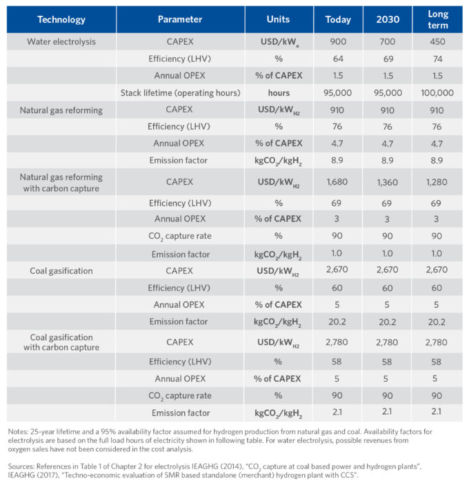
TABLE I.
Comparison of Capex, Opex, Efficiency and CO2 Impact of Hydrogen Production Routes (1)
EAF CO2 GENERATION
Electric Arc Furnace (EAF) based mini mills (MMs) produce 28% of world steel, though they account for only 8% of the CO2 generated by the steel industry. On the other hand, conventional integrated mills (blast furnace/basic oxygen furnace [BF/BOF] route) produce 72% of world steel with a higher CO2 generation rate (92%), as shown in TABLE II (1, 7).
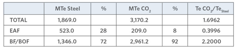
TABLE II.
CO2 Generation by Steel Mill Type (1, 7)
The volume of CO2 can be diminished significantly from that of the BF/BOF route with the incorporation of H2, renewables, and scrap, as shown in Figure 2a (5, 8). Figure 2b shows CO2 emissions intensity by country.
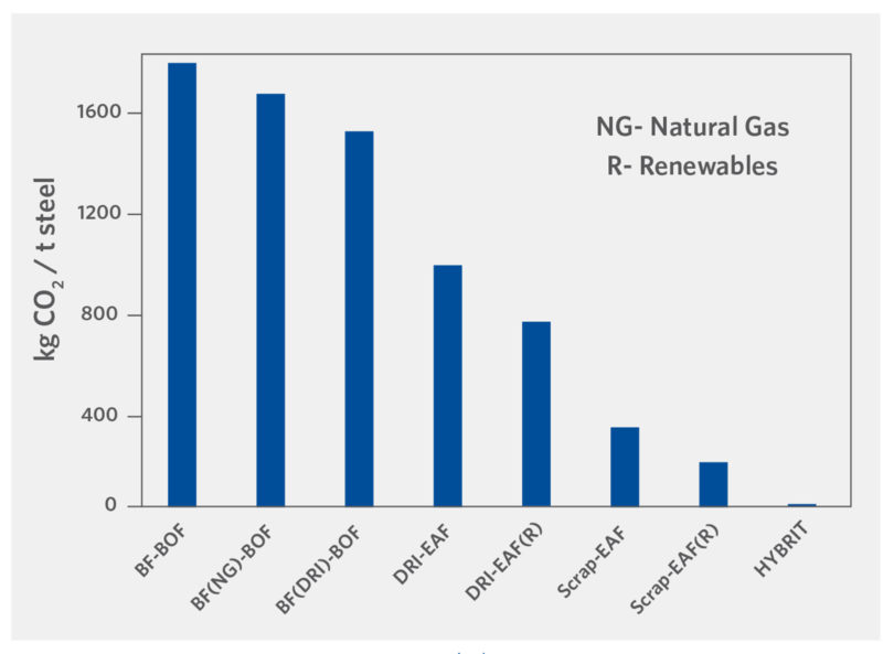
FIGURE 2a.
CO2 Generation by Steel Route (5, 8)
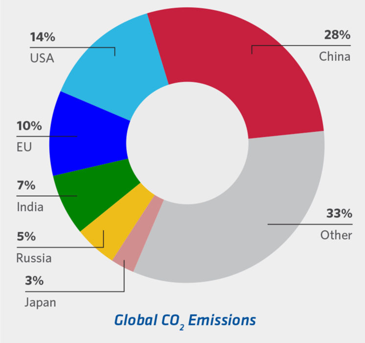
FIGURE 2b.
CO2 Generation by Country (7)
TABLE III identifies some EAF CO2 sources(9), from power generation (50-70% energy input to the EAF [see Figure 7]) to combustion of C from the bath, dirt on scrap, in-situ C (liquid steel, scrap, PI, DRI, HBI, MagCarbon bricks, electrodes, charge C, injection C), and lime production.
CO2 remediation is focused on the EAF route, despite the smaller impact it presents, because the EAF route is regarded as the easiest, most economical conversion option. The EAF route has lower reliance on diminishing quality iron ore sources (i.e., predominantly scrap-based), has a current global recycle rate of 80-90%, and uses only 1/8th of the energy compared to conventional integrated mills.
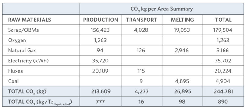
TABLE III.
CO2 Sources in EAF Steelmaking (9)
Scrap-based EAF operations present the most CO2 friendly route (Figure 3) even when including electricity contributions (assuming 65 kg CO2/Te DRI and about a 15% scrap charge in the BOF). However, the beneficial continuous recycling in the EAF will render prime scrap sources few-and-far-between long term (Figure 4), necessitating greater use of Ore Based Metallics (OBMs – DRI/HBI and Pig Iron) and Hot Metal. This need will be greater for high quality steel mills with stringent residuals requirements. Figure 5 shows the residual levels (and yield) of various metallics and specific steel quality needs. Significant variation in C (0.08% in sheet to 0.4% in rebar) and detrimental copper (Cu – 0.33% in structural to 0.04% to 0.1% in sheet) between scrap grades means that to produce a 0.08% Cu steel today (with USA scrap currently containing 0.25-0.3% Cu), a 70% OBM charge is needed.
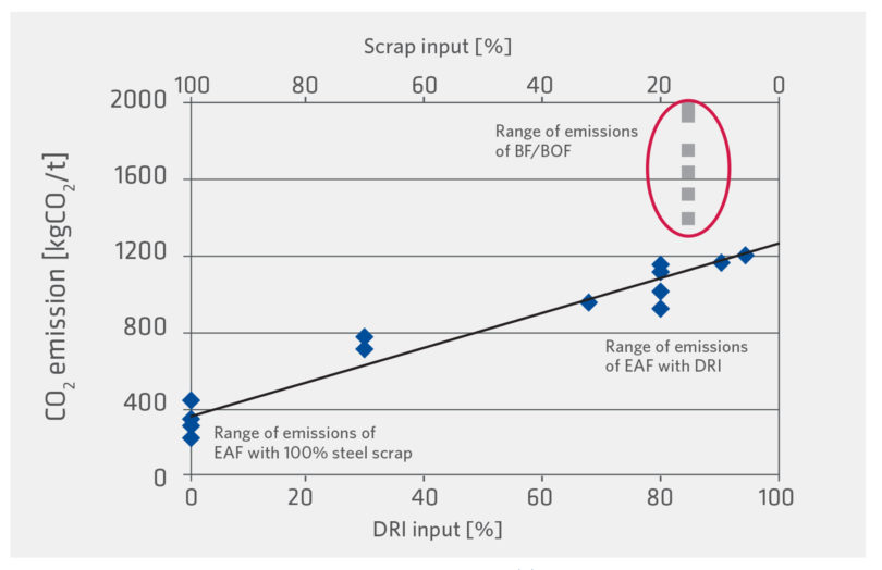
FIGURE 3.
Impact of DRI on steelmaking CO2 emissions (10)
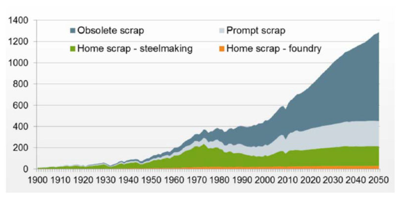
FIGURE 4.
Global Scrap Availability (Million Tonnes)
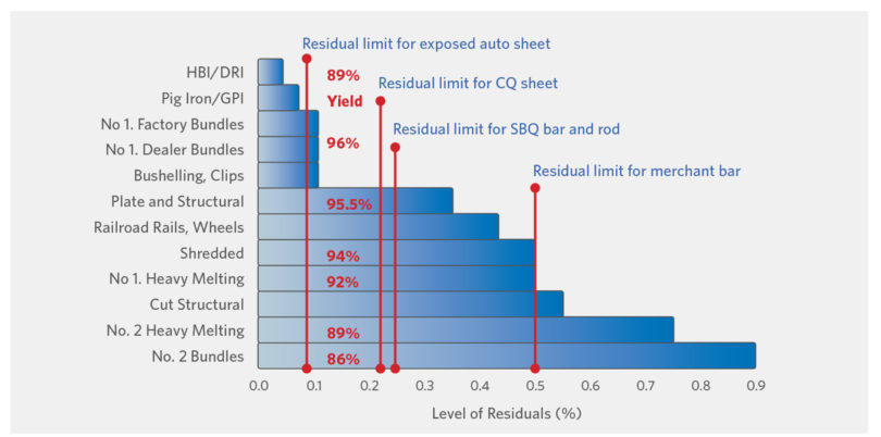
FIGURE 5.
Residuals Level and Yield by Metallics Type (11)
Whilst there will be plenty of obsolete scrap moving forward, meeting quality steel chemistry constraints will require the industry to demand changes in scrap handling, such as a global agreement on an international standard scrap nomenclature and specification and better segregation. Cost premiums for guaranteed prime quality scrap will undoubtedly result.
Since the EAF charge constitutes 76-89% of the cost of a tonne of liquid steel (Tels) a stringent value in use (VIU) model will be required to maximize EAF steelmaking profitability by minimizing liquid steel costs. This will need to be an all-encompassing VIU charge model [11] reflecting value not only for composition (low residuals, C content, and gangue) but also physical properties of raw materials, benefits and potential operational impacts (11), an environmental impact minimization algorithm, and if large scale H2 DRI production capacity becomes a reality, 0% CDRI and its impact on slag volumes and chemical energy. How will they impact productivity, yield and operational costs?
BENEFITS OF CARBON IN EAF OPERATIONS
Steel is an alloy of iron (Fe) and carbon (C); therefore, ‘zero carbon steelmaking’ is a contradiction. The term ‘carbon neutral steelmaking’ is a more accurate descriptor. Accepting that large amounts of H2 can be incorporated into the MIDREX Shaft Furnace, and that the reaction between H2 and iron oxide will proceed similarly as with the mixture of CO/ H2 produced from natural gas (NG) and iron oxide (FeO), the absence of CO will result in an endothermic reaction (requiring heat balance adjustment) and no DRI carburization. This resultant zero carbon DRI (0% CDRI) will create most of the issues when considering EAF melting.
EAF melting has changed dramatically since 1965 (12), predominantly through a significant increase in chemical energy use, now 35-50% of melt energy (Figure 6). This chemical energy is derived from O2 (sourced from O2 injection, excess O2 from oxy-fuel burners, or bath reduction) combusting with a fuel (NG, etc.), C in the charge or bath, and other elements in the bath (Fe, Si, Al, etc.). This high chemical energy input has required process optimization for energy, charge materials, and carbon sources.(11,12)
Historically, C was added as charge C. This was followed by C injection and in-situ carbon from OBMs (PI, HM and low-to-high C HBI/DRI). In the early 90s, DRI C was between 1.6% and 1.8%C because most mills lacked O2 tools/supply to decarburize the melt, leading to longer tap-to-tap times, reduced productivity, and higher steel costs since productivity value was at a premium versus reduced energy costs. Interest in ‘high % C DRI’ rose with improved O2 tools, larger off-gas systems (OGS), and knowledge and acceptance of the VIU of in-situ CDRI.
Today, CDRI can range from 1% (HBI) to 4.5% (DRI), process and reductant dependent(13), though most mills operate between 1.5% and 3.5%. The optimal % C is controversial, even changing plant-to-plant within the same steel group.(14)
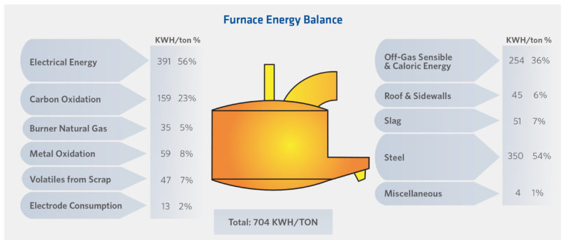
FIGURE 6.
EAF Energy Balance (12)
At 100% efficiency, C will combust to produce 9.09 kWh/kg C. In-situ CDRI efficiency is > 95% (versus 24% to 76% for charged or injected C (7, 11, 12)). TABLES IV (9) and V (7) and Figure 7 show the potential C contribution to EAF energy, power, productivity, yield, and electrode wear [14]. The impact of EAF CDRI benefits versus lost DRI plant productivity and costs in a captive DRI/EAF plant are site specific, even within companies – Arcelor-Mittal (AM) East Montreal runs 2.0-2.2% C whilst other AM plants run at 2.2-2.7%C. (14)
The benefits of DRI in-situ C are many. Unlike charge C, C in DRI contains no ash, sulfur, or volatiles, which are detrimental to the melt process and/or steel quality. The combustion efficiency is much higher and, after C has reduced the FeO in the DRI (FeODRI), the excess C is available for chemical energy input (see a typical energy balance shown in TABLES IV and V). For example, at 95% met and 93% FeTotal, 1.4% C reduces 67% FeODRI and 0.75%-1.75% excess C is available for combustion depending on % CDRI (1.8%-2.0% C in this example).
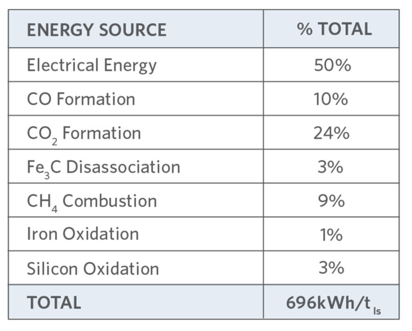
TABLE IV.
EAF Energy Sources Today (9)
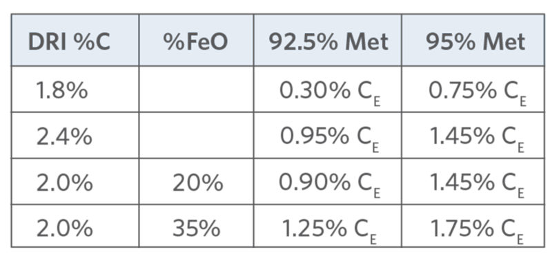
TABLE V.
Excess Carbon by DRI %C & %Met (7)
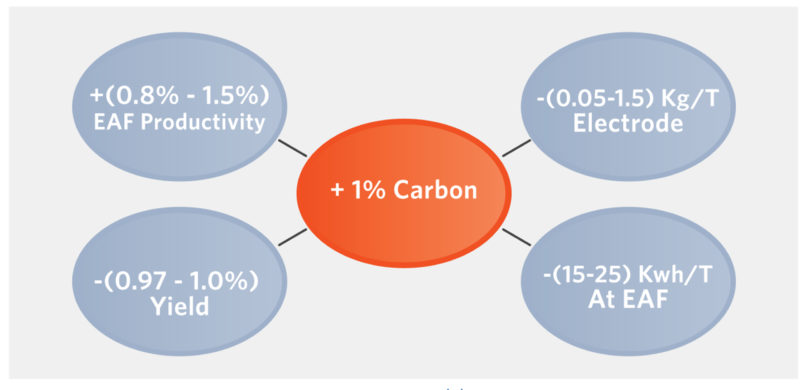
FIGURE 7.
Effect of 1% CDRI on EAF Operations (14)
The reduction of the FeODRI by the CDRI completes the metallization. The chemical energy generated from the excess CDRI reduces the kWh/Te, power-on time, and tap-to-tap, and thus increases productivity. The CO generated from the combustion foams the slag creating a foamy slag, increasing the slag’s surface area, improving removal of undesirable elements from the steel (including N, H, S, and P), and ‘refining’ it. As the foamy slag buries the electrodes, heat transfer/thermal efficiency is improved (> 93%), further shortening power-on time (POT), tap-to-tap time (TTT), and reducing kWh/Te. Figure 8 shows some of the EAF reactions.(15) Increased CDRI compensates somewhat for increased kWh/t required to melt DRI (presence of gangue) versus scrap and, because (FeO)slag is decreased, refractory life increases.
With high chemical energy input to the EAF, OGS losses (as high as 36%) must be minimized (Figure 6 and 7, TABLE IV). Energy optimization, using off-gas analysis, identifies sources of non-combusted ‘fuels’ exiting the EAF (CO, O2, H2, C) and allows adjustment of C, O2, oxy-fuel burners, volumes and injection angles. (12) Process optimization and OGA has highlighted the need for efficient C sourcing, optimal O2 solutions, as well as good foamy slag practice and optimum raw materials to lower kWh/Te, TTT/POT and electrode wear, and increase yield and productivity whilst producing quality steel.
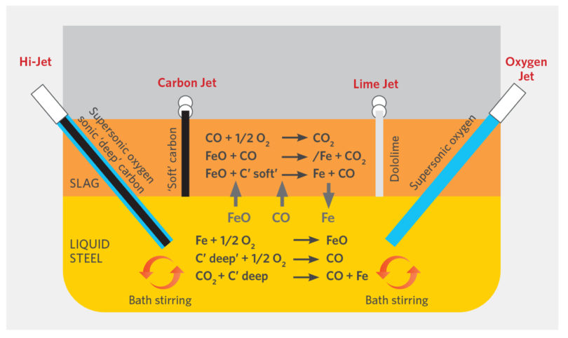
FIGURE 8.
Basic EAF Bath Reactions (15)
USE OF DRI/HBI IN THE EAF
One of the main reasons for using DRI/HBI is the consistently low residual content which provides predictable chemistry control of the liquid steel. Blending DRI/HBI with low cost-lower quality obsolete scrap can improve the overall cost of producing quality steel. Where scrap supply is poor or non-existent, captive DRI plants can all but alleviate metallics sourcing issues.
If standard operating procedures (SOPs) are optimized to take advantage of the unique chemical, thermal, and continuous charging properties of DRI, major benefits are available, perceived disadvantages such as excess consumables and slag (primarily attributed to gangue content) can be negated whilst operations and costs can be improved(7, 11, 20) with educated use and process optimization. In-situ CDRI (or CPI) with >95% efficiency (assuming the C is aligned with the available O2 tools and OGS size) can reduce the kWh/Te, despite the gangue content. (8, 17, 20) Nucor AK found melting 50% DRI could be done with lower kWh/ton and TTT than 100% scrap heat (see TABLE VI and (16)).
Some of the cost benefits have been quantified:
- Continuous feeding DRI can save $29.50/Te (no roof swings)
- Exceeding the optimal feed rate can cause ‘icebergs’ (more so with HBI than DRI)
- Hot DRI (HDRI) charging saves 20-30 kWh/100o C or $5-10/Tels (8, 11, 20)
- Slower initial feeding without O2 to a colder bath is required to prevent excessive C boils
- Optimization is a must to avoid greater off-gas volume and energy loss with high % C and HDRI
A cost benefit has not been assigned to the reduced N, H, and inclusions resulting from flushing by CO generated from the in-situ CDRI, nor the benefits of a faster and earlier formed foamy slag (improved arc stability, energy transfer; lower electrode wear, kWh/Te, noise). BHP (17) reported 100% DRI reduced [N]melt from 80 ppm to 10 ppm and [N]billet from 115 ppm to 28 ppm versus 100% scrap and increased refractory life and yield, as FeO recovery was improved.
Educated use has meant high quality steel producers, who sought less variable chemistry and downstream optimization, are no longer the sole DRI users.
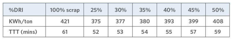
TABLE VI.
Nucor AK Results using DRI (16)
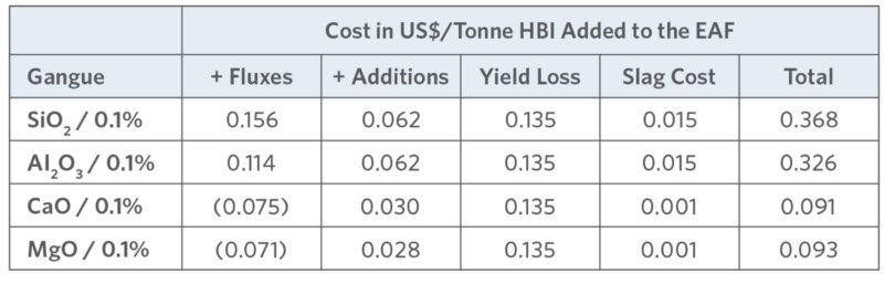
TABLE VII.
Impact of gangue in Asian mills (17)
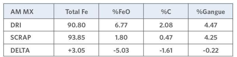
TABLE VIII.
AM MX Gangue Comparison (7,20)
IMPLICATIONS OF 0%C DRI/HBI
Over 300,000 Te of 0% carbon H2 DRI were produced on an industrial scale at the Circored Plant in Trinidad, using a two-stage fluidized bed process (15). A melting trial of some of the 95% met, 0% C CircalTM HBI was conducted at North Star Steel Texas, with the melting results being published in 2001 [18].
The results of the initial melting trial determined:
- Melt shop SOP required modifying
- Injection of C to the slag was required to control FeO (28%-35%)
- C and O2 injection were needed to stir the bath, reduce the FeO, and assist in creating a foamy slag
- Feeding high % DRI with scrap continuously into large heels produced the best results and avoided forming icebergs if the feed rate was properly matched to the heat input
- Significant decrease in residual levels was obtained, as expected
- Fe recovery from the FeODRI was achieved if sufficient alternative C was added to the furnace
- No clumping or icebergs occurred when 18.2 Te of HBI were charged as a single bucket layer
- Charge densification resulted in a reduction in POT
- No mechanical issues (shipping, transfer, and charging) were experienced
- Phosphorous removal was good and sulfur behavior was normal
- The increase in FeOslag attributable to HBI was minimal, but there were problems achieving the low nitrogen specifications and maintaining a good foamy slag due to lack of CO boil
In a subsequent trial, significant changes were made to the melt shop SOP:
- O2 injection was delayed resulting in higher electrical energy use
- Foamy slag was improved using a high pig iron charge and more injectable C to meet nitrogen specifications assist in creating a foamy slag
- Low residual levels were met using a large amount of pig iron
- HBI could only ever partially replace PI (22Te HBI charged)
This plant experience processing the 0%C Circal HBI suggests more energy will be required to melt 0% C DRI. This will create more CO2 emissions from power generation unless ‘green’ energy is available (0.295kg-1.005kg CO2/kWh – World Steel Association states 9.8GJ Fuel/MWh electricity) – as well as a need for alternative C sources unless pig iron is used, which then involves BF CO2 emissions.
The projected future dearth of DR-grade iron ore (67% Fe or greater) will compound the increased EAF energy requirement because lower Fe ores, similar to what is currently processed in blast furnaces, would need to be used in DRI facilities. There would be no CDRI to reduce the FeODRI and complete the metallization. Incomplete metallization and missing CDRI will increase the amount of gangue in the system, FeOslag, and contribute to yield loss unless substantial C is added to the EAF (per current operating guidelines). Therefore, 0% carbon hydrogen-based DRI, coupled with poor ores, would negate the benefit of using hydrogen unless the energy used in the EAF was clearly ‘green.’ If not, the overall carbon footprint will not be lowered.
There is a clear need for a thorough analysis of all the issues. Developing sufficient renewable energy capacity for EAF steel production is a significant issue itself with immense additional challenges of finding affordable ‘green’ H2 production routes. All opportunities depend upon ‘green’ power and H2 supply volumes reaching required levels at acceptable prices – both extremely challenging. H2 is currently cost-prohibitive (requiring 800MW/Te DRI), especially when compared to the much cheaper current C tax for steelmaking (25EU/Te CO2 versus $350-$450/Te CO2 mitigation). (4, 5)
Other important effects to consider when assessing the value vs. environmental impact of replacing natural gas with hydrogen in the DRI process include:
- The temperature at which steel melts increases with decreasing % C, requiring more energy.
- Thermodynamically, low carbon steels are associated with high FeO content slags, so there would be potentially lower yields unless the FeOslag is reduced after the initial melting stage.
- There will be less available in-situ chemical energy in the DRI.
- Other C sources will be needed for FeODRI reduction, foamy slag production, bath stirring, chemical energy, flushing of nitrogen, hydrogen, and other undesirable elements. Unless the alternatives are ‘green,’ they will have their own CO2 emissions issues. Additionally, twice as much carbon is likely to be required if not in-situ, adding more CO2.
- Bath stirring will be required: carbon injection or bottom porous plug or tuyeres using nitrogen, argon or CO2 (or even O2 with natural gas). Industrial gas production requires more power. It could be possible to capture CO2 and use it for stirring (19) but there will be costs and challenges associated with cooling and cleaning the CO2.
- Refractory wear is likely to increase (C dissolution, longer melt times, and FeO erosion) unless refractory systems are re-thought.
- Potential for icebergs, which will slow feeding rates, lengthen POT, reduce productivity, and increase power use.
- Bath reactions will be slower, which will lengthen POT, reduce productivity, and increase power use.
- Lack of foamy slag means more slag volume will be needed to bury the electrodes, maintain thermal efficiency (> 93%), reduce noise, and refine the steel, all of which likely will require a deeper bath. Also, additional slag formers will be required and disposal requirements will increase, thereby increasing costs.
Assessing the cost implications of 0% C DRI in the EAF would be very broad and site specific depending upon the quality of the ore, metallics, and scrap; the specific local costs for the consumables; the value of potential lost productivity; availability and type of power and H2; and effluent (slag, in-house scrap, and dust) disposal and potential value.
Any future scrap-based steelmaking will require that the global scrap industry agrees to identify and segregate scrap materials along compositional lines to ensure lowest cost steelmaking. Adoption of ‘green’ steelmaking needs to be global to ensure equitable sharing of costs and technology development and equitable global steel pricing, not to mention significant inroads in addressing the global warming issue (USA and EU together produce less CO2 than China alone [see Figure 2b].
CONCLUSIONS
There is evidence that producing economical DRI without CO2 emissions is feasible assuming ‘green’ H2 is forthcoming or ‘blue’ H2 is adopted as a compromise. If H2 DRI production develops as a major technology, with its resultant zero carbon DRI, EAF steelmakers will be challenged to:
- Provide sufficient stirring in the bath for refining without carbon-generated CO
- Provide sufficient slag foaming without carbon as a foaming agent
- Ensure that there is not significant yield loss through high FeO formation
- Limit loss of productivity through long melt down times and formation of ‘icebergs’
- Ensure the availability and use of renewable electricity to prevent nullification of the environmental advantage of using H2 to make DRI
Hydrogen DRI production is an exciting development but there are significant technical and economic challenges around both the ironmaking and steelmaking steps that need to be addressed. To compensate for the issues, we will need SOP changes, ‘green’ power sources, alternative carbon and chemical energy sources, and possibly a new EAF design – shape and size, stirring capability – or, better still, a completely new steelmaking process. Certainly, with less carbon to remove, the steelmaking step will have more emphasis on gangue removal, control of phosphorus, residuals, and dissolved gases. In a re-configured EAF steelmaking process designed for a 95% charge(1) of 0%C DRI, semi-continuous feeding of DRI into a deep bath with inert gas stirring could help overcome concerns with icebergs and yield loss and, hopefully, address productivity.
References
- International Energy Authority (IEA) G20 Hydrogen Report: “The Future of Hydrogen and Assumptions”
- IEA Iron and Steel Technology Road Map – “Towards a Sustainable Steelmaking”
- “Material Economics – A Powerful Force for Climate Mitigation,” IEA ETP, Beyond 2*C Scenario.
- “Ultra-Low CO2 Ironmaking: Transitioning to the Hydrogen Economy,” 1Q DFM 2020, V. Chevrier.
- “Hydrogen DRI: cost and strength issues,” G. Kim & C. Pistorius, Carnegie Mellon University, Wilton E. Scott Insti- tute for Energy Innovation, Center for Iron and Steelmaking Research, AIST DRI Committee Presentation, May 2020.
- “Hydrogen for Australia’s Future,” Commonwealth of Australia, August 2018.
- “Evaluating the Viability of H2 Generated DRI in the EAF,” Australian, NZ 2nd Annual Steel Seminar, Nov. 2020, S. Hornby.
- “Future Green Steelmaking Technologies,” ISS EF Confer- ence 2002, S. Hornby-Anderson, G. Metius, J. McClelland.
- Private conversations with J.A.T. Jones regarding his presentations for IIMA.
- “The Hydrogen Route to Ironmaking – Options and Implications,” Presentation at the Australian Ironmaking. Conference at Newcastle University, NSW Australia. Nov. 2020, G. Brooks.
- “Mini-Mill Burdening for Maximum Efficiency and Yield,” Iron and Steel Technology, Jan 2015, P50, S. Hornby.
- “Comparison of Shaft and Conventional Furnace Combustion Efficiency,” ISS EF Conference 1998, S. Hornby-Anderson, M. Kempe, J. Clayton.
- “Results of Lab Trials of Midrex ACTTM,” 3Q DFM 2019, V. Chevrier, M. Arandas.
- “The Value of DRI – Using the Product for Optimum Steelmaking,” 1Q DFM 2015 and AMM Scrap and DRI Melting, New Orleans, LA, S. Sunyal.
- “Circored fine ore reduction – the future of the modern electric steelmaking”, Stahl und Eisen, 126, 3, 2006 p. 47-5, D. Nuber, H. Eichberger and B. Rollinger.
- “Flexibility in EAF Operations with DRI,” AMM 3rd Annual DRI-Mini-Mill Conference 2015, T. Tirabassi.
- Use of DRI and HBI for Nitrogen Control of Steel Products, ISS EF Conference 2002, S. Hornby-Anderson, D. Trotter, D. Varcoe, R. Reeves.
- “Use of CircalTM in EAF Steelmaking at North Star Steel Texas,” ISS EAF Conference 2001, D. Lockmeyer, B. Yalamanchili
- “CO2 in Steelmills,” ISS EF Conference 1989, S. Hornby-Ander- son, D. Urban.
- “Educated Use of DRI/HBI Improves EAF Energy Efficiency & Yield and Downstream Operating Results,” European EAF Conference, May 2002, Dr. S. Hornby-Anderson.
Related Reading
 Mar 25, 2026
 Feb 04, 2026