
Oxygen Injection at Acindar – Boosting MIDREX® Plant Performance

Geoff WallworkGlobal Solutions Principal Engineer
Articles by Geoff
INTRODUCTION
There are various designs of the oxygen injection system presently installed in MIDREX® Direct Reduction Plants.
These designs range from the original system installed at SIDOR in Venezuela, where air and oxygen were simply injected into the reformed gas duct, to the first oxygen injection nozzles installed in the enrichment natural gas ports at Acindar* in Argentina, to similar systems installed in recent years with minor variations to the original design. While oxygen injection systems have become a common feature in many MIDREX Plants, Midrex continues to research potential improvements to the system, especially with the advancement of Computational Fluid Dynamics (CFD) modeling.
This article will trace oxygen injection from research and modeling to improvements in the new system implemented at the Acindar plant. We will present an overview of the oxygen injection system, as it is helpful to understand the purpose of oxygen injection and its relationship to the operation of a MIDREX Plant. Then we will discuss recent design and operational changes to the oxygen injection system developed through CFD modeling and implemented in the Acindar plant.
PURPOSE OF OXYGEN INJECTION
Reduction reaction rates occurring inside the shaft furnace increase as the temperatures in the reduction zone increase. There are limitations on how much the temperature can be increased but generally, for each 10° C increase in the bustle gas temperature, a plant can realize 1.5-2.0% increase in production.
The oxygen reacts exothermically, producing mostly H2O and CO2, thereby raising the bustle gas temperature before reaching the furnace. When the oxygen reacts with methane in the bustle gas, it also will generate H2 and CO, thereby increasing the bustle gas flow. Part of this increase is achieved when oxygen reacts with methane from the reformed gas and the enrichment natural gas in the bustle line, and part is achieved when the bustle gas enters the furnace bed and reaches equilibrium through reforming and carbon deposition reactions on the DRI (acting as a catalyst), referred to as in-situ reforming.
There is a drop in temperature from the bustle gas to the bed temperature due to the endothermic reforming and carbon deposition reactions as they go to equilibrium. So, there are two factors at work: 1) additional bustle gas flow with additional H2 and CO for reduction, and 2) additional temperature not only in the bustle gas but more importantly in the furnace bed where it will improve the reduction kinetics.
Without oxygen injection, the maximum bustle gas and bed temperatures are limited by the reformed gas temperature exiting the reformer minus heat losses due to the piping, as well as the addition of relatively cooler enrichment natural gas. To overcome these temperature losses and raise the bed temperature, oxygen may be injected at the reformed gas mixer.
However, there are limitations. The upper limit of oxygen injection is determined primarily by the maximum bustle gas temperature allowed before coated DRI starts to form clusters and disrupts the material flow in the furnace. It should be noted that the oxide should be coated prior to entering the furnace to permit higher reduction zone temperatures and minimize the potential for clustering. The amount of oxygen utilized by a particular MIDREX Plant will vary but is typically ~15 Nm3/t DRI.
PURPOSE OF ENRICHMENT NATURAL GAS
It is helpful to understand the role of enrichment natural gas when discussing oxygen injection, as these gases are being injected in the same location within the plant. Common to all MIDREX Plants, natural gas is injected into the reformed gas at the reformed gas mixer. This natural gas injection is referred to as enrichment natural gas (ENR). Adding enrichment natural gas to the bustle prevents uncontrolled methanation reactions from occurring in the shaft furnace. When enough methane is added, the reaction between methane and CO2 and H2O shifts to reforming and generates reductants for reducing the oxide and promotes in-situ reforming in the shaft furnace.
In-situ reforming is the reforming of natural gas over the metallic iron in the reduction zone of the furnace. The metallic iron acts as a catalyst to increase the rate of the reforming reaction. To promote in-situ reforming, it is necessary to have three key parameters: heat, oxidants, and hydrocarbons (methane or higher). Sufficient heat must be available, as the reforming reaction is endothermic. By increasing bustle gas temperature, oxygen injection provides the heat necessary for the in-situ reforming reactions, as described in Figure 1.
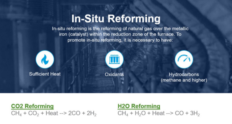
FIGURE 1.
In-situ reforming reactions
Oxidants (CO2 and H2O), as well as hydrocarbons (CH4 and higher) must be available to react and form the reductants (CO and H2) for in-situ reforming. Oxidants are available from the bustle gas CO2 and H2O, while hydrocarbons are available from the enrichment natural gas.
With sufficient heat, methane, and oxidants, the reforming reaction proceeds to the right (see Figure 1), forming the reductants until reaching equilibrium in the reduction zone. If there is insufficient methane, the reactions proceed in the reverse direction to the left (see Figure 1), producing methane and is referred to as methanation. This direction is undesirable.
Enrichment natural gas also is used to increase the amount of carbon in the direct reduced iron product. Once enough enrichment natural gas is added to prevent methanation, the operator has the flexibility to add additional enrichment natural gas depending on the type of product and amount of carbon desired. The hydrocarbons in the enrichment natural gas “crack” to form carbon and hydrogen. The carbon is deposited on the bed, while the hydrogen becomes additional reductant in the furnace.
Oxygen Injection System Description
The oxygen injection system can be divided into two parts: the oxygen injection control skid and the reformed gas mixer. They are highlighted on this drawing of the oxygen injection system (Figure 2).
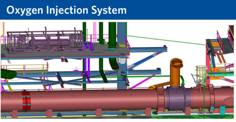
FIGURE 2.
Locations of oxygen injection control skid and reformed gas mixer.
Oxygen Injection Control Skid
The oxygen injection control skid (see Figure 3) typically is located near the reformed gas mixer. The control skid contains the equipment and instruments required for controlling the flow and pressure of the oxygen. The control skid also contains the purge gas accumulator and controls required for purging the oxygen nozzles before and after oxygen injection operation. The horizontal tank is the purge gas accumulator. The control skid has not undergone any significant changes and is not a primary focus for improvement.
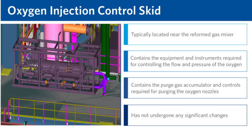
FIGURE 3.
The oxygen injection control skid.
Reformed Gas Mixer
The reformed gas mixer is located on the reformed gas duct between the reformer and the shaft furnace. The enrichment natural gas is injected through a type of bustle ring header, shown in Figure 4. The natural gas fills the bustle ring header and enters the reformed gas duct typically through eight ports. Once the operator enters the desired bustle gas percent methane, the flow of enrichment natural gas is modulated by a control valve to achieve the desired methane percentage. The methane analyzer provides the measured methane content in the bustle gas and adjusts the flow of enrichment natural gas accordingly.
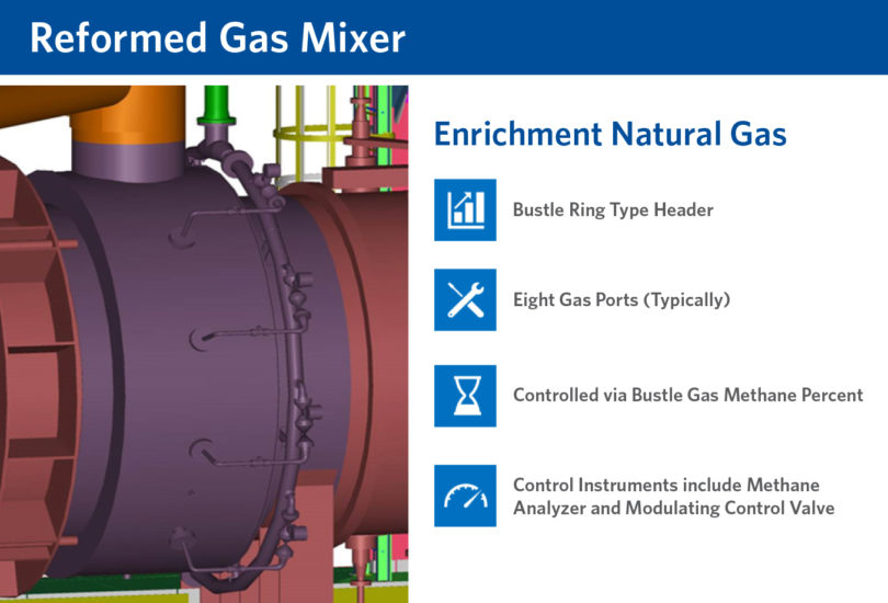
FIGURE 4.
The reformed gas mixer - enrichment natural gas.
Figure 5 shows both an outside and inside picture of the reformed gas mixer. In the outside picture, you can see the natural gas inlet pipeline and the bustle ring header. Note that the mixer includes oxygen injection with the nozzles inserted into the enrichment natural gas ports. The inside picture shows the brick orifice, enrichment natural gas ports and the oxygen injection nozzles.
The reformed gas mixer is also the location for injecting oxygen into the reformed gas duct. The oxygen nozzles are inserted into the enrichment natural gas ports. By locating the nozzles in these ports, the enrichment natural gas provides cooling to the oxygen injection nozzles. The oxygen nozzles slightly protrude from the enrichment natural gas ports.
The brick orifice upstream of the oxygen nozzles and enrichment natural gas ports protects the flames from being blown out by the reformed gas and allows the flames to be sufficiently away from the refractory wall.
Once the operator enters the desired bustle gas temperature, the flow of oxygen is modulated by a control valve until the desired bustle gas temperature is achieved. Control logic will automatically open and close oxygen nozzles per a set sequence based on the total oxygen flow required to achieve the desired bustle gas and bed temperatures.
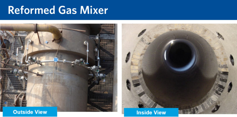
FIGURE 5.
Reformer Gas Mixer- Outside / Inside Views
RECENT SYSTEM DESIGN CHANGES
To gain a better understanding of the typical system, a CFD model was generated of the duct between the reformer and the shaft furnace, which includes the reformed gas mixer (Figure 6). At Acindar, there is a second smaller 90-tube reformer that can feed additional reformed gas into the system. This is labeled as the secondary RG inlet in the model picture. Once the model was generated for the system, changes were implemented and studied to develop an optimized system based on the modeling results.
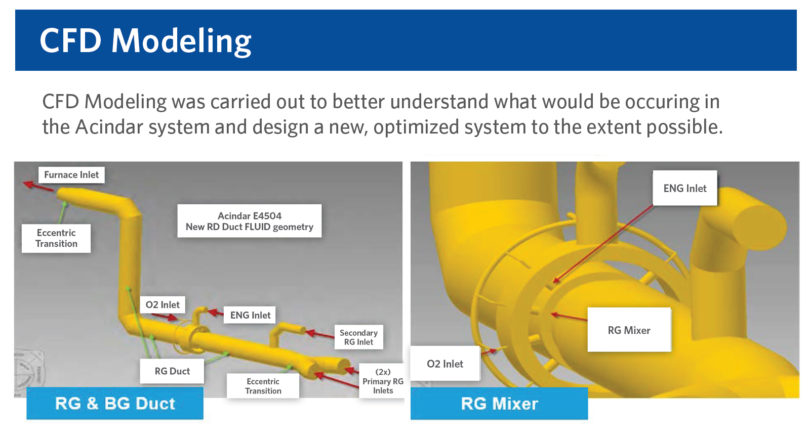
FIGURE 6.
CFD Modeling
At the beginning of the study for optimizing the oxygen injection system for Acindar, there were three primary goals:
- to increase the flexibility of the oxygen injection system. The target was to accommodate a wide range of reformed gas, oxygen, and enrichment natural gas flows over a broad range of production rates, all while maintaining a stable and reliable flame at the oxygen nozzle. Typically, oxygen injection is used as a sort of booster once the reformer is nearing its capacity. However, ArcelorMittal Acindar has determined that oxygen injection has a benefit even if the reformer is not at full capacity. Acindar desired the flexibility to operate oxygen injection at both relatively low production rates as an example when suffering natural gas curtailments, or low market, as well as at high production rates.
- to improve the oxygen injection nozzle life. The oxygen injection nozzle is primarily protected with the enrichment natural gas acting as a shroud gas. However, relatively high temperatures can be present at the nozzle tip with the potential for damage to the nozzle.
- to improve the refractory life, especially in the area of the oxygen nozzles on the reformed gas mixer. The same relatively high temperatures that could potentially damage the nozzle tips could also potentially shorten the life of the refractory in the duct.
PRIMARY SYSTEM CHANGES
After extensive CFD modeling, changes were made to the system to achieve the stated goals. The primary changes included the enrichment natural gas (ENG) port diameter, the oxygen injection nozzle tip penetration into the duct, minimum and maximum flows for oxygen and for enrichment natural gas, and the addition of a secondary enrichment natural gas port.
ENG Port Diameter
After review of the CFD models, an optimum velocity range for the enrichment natural gas at each port in the reformed gas mixer was determined. This velocity range ensured adequate cooling of the oxygen nozzles and refractory wall while maintaining a stable flame at the nozzle. To achieve the optimum velocity range, the enrichment natural gas port diameters were decreased.
Oxygen Injection Nozzles Velocity
Similar to the enrichment natural gas, an optimum velocity range for each oxygen injection nozzle was determined. The optimum velocity range maintained a stable flame while penetrating further towards the center of the reformed gas duct and away from the refractory wall. To obtain the optimum velocity range, minimum and maximum oxygen flows per nozzle were determined. Control logic was established to automatically open and close the individual nozzles as required based on maintaining the oxygen velocity while reaching the desired bustle gas temperature.
Figure 7 shows an example of the velocity vectors at the enrichment natural gas port and oxygen nozzle from the CFD model. The enrichment natural gas port is shown in blue and the oxygen nozzle is shown in green.
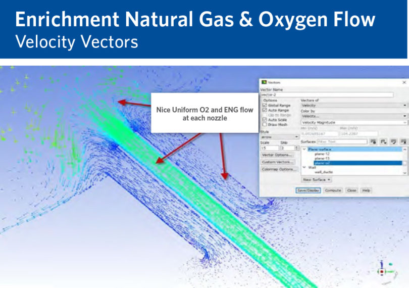
FIGURE 7.
Enrichment natural gas port and oxygen nozzle.
Oxygen Nozzle Tip Penetration
Various oxygen nozzle tip penetrations were modeled and reviewed. Penetration is defined in this article as how far the nozzle tip protrudes into the reformed gas duct beyond the refractory wall. To determine the optimum penetration, various parameters were reviewed including the flame shape, temperature at the nozzle tip and the refractory wall temperatures.
An optimum penetration length provided acceptable temperatures at both the nozzle tip and refractory wall.
Figure 8 is an example of the CFD model when comparing two different nozzle tip penetration lengths. On the first model (Detail 2.1.1), the temperature profile at the nozzle tip is relatively high, so it was recommended to change the penetration length. In the second model (Detail 2.1.2), the penetration length has been decreased, and the temperature profile at the nozzle tip is much cooler.
Also, from these models, it can be seen that the temperature profile at the refractory wall or hot face is relatively cool and should lead to an improved life of the refractory. (Note that the flames reach temperatures as high as 2500° C.)
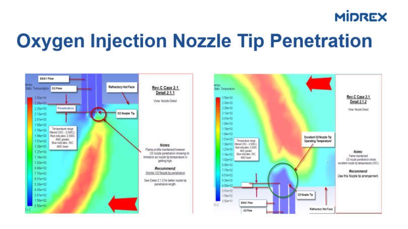
FIGURE 8.
CFD model when comparing two different nozzle tip penetration lengths
Min and Max ENG flows
The CFD modeling also determined the minimum and maximum flows of enrichment natural gas when operating with oxygen injection. The range of flows had to provide a stable flame when varying the reformed gas flow and oxygen flow while sufficiently cooling the oxygen nozzle and refractory wall.
It was determined that the maximum enrichment flow allowed at the oxygen nozzles was less than the amount of enrichment natural gas required to produce high carbon DRI at high production. Therefore, a secondary enrichment natural gas inlet nozzle was added to the bustle gas downstream of the reformed gas mixer (Figure 9). By splitting the enrichment natural gas flow between the reformed gas mixer and the secondary inlet nozzle, the plant has the flexibility to operate within the full range of enrichment natural gas flows. The flow at the reformed gas mixer can be safely limited when operating with oxygen while the secondary inlet fulfills the requirements for high carbon product at high production.
As an additional benefit to limiting the amount of enrichment natural gas flow at the reformed gas mixer, the ratio of oxygen to natural gas (methane) is controlled to a more optimal range to minimize soot or carbon formation in the bustle gas duct. Midrex is continuing to investigate options to decrease carbon generation in the bustle gas duct and improve the quality of the reducing gas generated. Early indications from Acindar show minimal carbon deposition, as compared to the typical system design and operation.
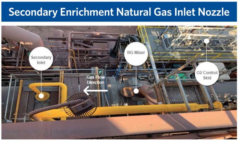
FIGURE 9.
Secondary enrichment natural gas inlet nozzle
SUMMARY
Oxygen injection leads to higher bustle gas temperatures and more reductants, which leads to higher bed temperatures and higher reaction rates in the furnace, which ultimately leads to an increase in production. Enrichment natural gas prevents methanation, increases product carbon, and promotes in-situ reforming in the furnace.
Midrex developed CFD models of the oxygen injection system to evaluate potential improvements. Primary targets included flexibility for ensuring a stable flame over a wide range of flows and production rates, improved oxygen injection nozzle life, and improved refractory life. As a result, the following design changes were implemented at Acindar:
- Decreased the enrichment natural gas port diameter to provide an optimum natural gas velocity range.
- Determined the optimum oxygen nozzle penetration into the duct for improving the life of the nozzle
- Determined the minimum and maximum flows of enrichment natural gas specifically at the reformed gas mixer. Control logic was modified to maintain the flow within the required range.
- Determined the minimum and maximum flows of oxygen injection to provide an optimum velocity range. Again, control logic was modified to maintain the optimum range of flows. The control logic automatically opens and closes the individual oxygen nozzles as required.
- Added a secondary inlet for the enrichment natural gas.
After implementing these changes, Acindar has reported the system is operating successfully over a range of production rates and the carbon generation in the bustle gas duct has decreased compared to the previous operation and system.
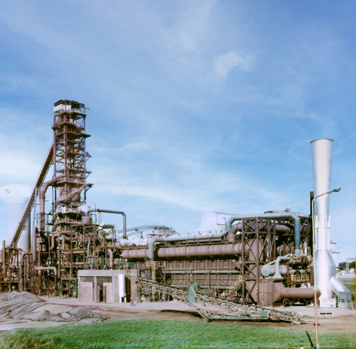
ACINDAR
*Founded in 1942 by a group of businessmen led by engineer Arturo Acevedo, Acindar Industria Argentina de Aceros S.A. (Acindar) is one of Argentina’s oldest steel companies. Its headquarters are located in the city of Villa Constitución and it has plants in the cities of Rosario , Villa Mercedes , La Tablada, and San Nicolás. Acindar merged with Arcelor subsidiary Belgo Mineira in 2001 and became part of the ArcelorMittal Group in 2006. ArcelorMittal has controlled 100% of the company since 2008.
Related Reading
Tech Article Electrical Heating of MIDREX® Process Gases
Read More Jun 28, 2023