
MIDREX NG™ with H2 Addition: Moving from natural gas to hydrogen in decarbonizing ironmaking

Todd AstoriaChief Technology Officer
Articles by Todd
Greg HughesManager - Process Analysis
Articles by Greg
Noriaki MizutaniKobe Steel Ltd.
Articles by Noriaki
INTRODUCTION
A lot has changed in the world of iron and steel production in the last 50 years. The cost efficiencies of oxygen steelmaking – a method in which pure oxygen is blown into large quantities of molten blast furnace iron (hot metal) and scrap to oxidize impurities such as carbon, silicon, phosphorus, and manganese – sounded the death knell for open hearth steelmaking. Today, the majority of global steel production (about 66%) is produced in basic oxygen facilities. [1]
The emergence of the electric arc furnace (EAF) provided the coup de grace for the open hearth.* Initially used for specialty steels and the manufacturing of steel alloys, the EAF began competing for the production of carbon steels (long products). Because EAFs could be sized to meet the needs of a specific market and used local or regional scrap resources for their iron charge, they became known as mini-mills or market mills. The percentage of EAF-based steelmaking has been steadily increasing due to its flexibility, economy-of-scale, and cost-competitiveness and now accounts for about 33% of global steel production [1] and over 70% in the US [2].
On the ironmaking side, coke-fueled blast furnaces were producing large volumes of hot metal to satisfy the growing need for steel products to support global industrial expansion. Direct Reduced Iron (DRI), introduced commercially in the late 1950s, was viewed as a niche material for use in EAFs where vast amounts of steel were not needed or where adequate supplies of scrap were not available. However, progressive EAF-based steel companies took notice of the positive effect DRI had on inclusions in scrap and found that they could produce even the highest-grade steels – and at a cost that few traditional integrated steelmakers could match.
However, the use of significant percentages of DRI in EAFs has given rise to one of the biggest iron and steel industry facelifts in history – decarbonization. Steel production via the DRI-EAF route has the lowest carbon dioxide (CO2) emissions of any iron ore-based method. MIDREX® Plants based on clean-burning natural gas (MIDREX NG™) are seen as the most viable near-term response to the need to reduce CO2 emissions associated with iron and steel production. As the means of producing sufficient volumes of hydrogen at competitive prices develop for use as fuel and reductant in direct reduction plants, Midrex can modify existing plants to replace natural gas with hydrogen and design new plants to use up to 100% hydrogen for their fuel and reductant (MIDREX H2™).
IRON & STEEL CO2 INTENSITY
The direct CO2 intensity of crude steel has been relatively constant (within a 20% range) during the past two decades, and in the last couple of years has returned to roughly the 2000-08 level [3]. According to the International Energy Agency (IEA), the CO2 intensity of crude steel needs to fall an average of 2.5% annually between 2018 and 2030. Achieving this reduction and maintaining it after 2030 will not be easy.
Energy efficiency improvements spurred much of the reduction in recent years, returning CO2 intensity to previous levels, but opportunities for further efficiency improvements will likely soon be exhausted. Thus, innovation to commercialize new low-emissions process routes, including those integrating CCUS (Carbon Capture, Utilization, and Storge) and hydrogen, in the upcoming decade will be crucial to realize the long-term transformational change required.
While the energy intensity of steel has gradually fallen since 2009, expanding production from 2009 to 2014 raised total energy demand and CO2 emissions. After a small decline between 2014 and 2016, energy demand and CO2 emissions increased in 2017 and 2018, primarily as a result of higher steel production. Based on total steel industry emissions (see Figure 1) and global annual CO2 emissions (52 Gt, as reported in UN Emissions Gap Report 2020, or 33 Gt in 2019, as reported by IEA), the global steel industry accounts for around 7-11% of total global CO2 emissions [4].
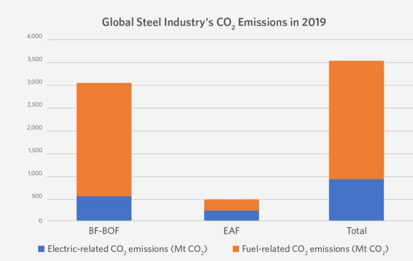
FIGURE 1.
The global steel industry emitted around 3.5 gigaton of CO2 emissions in 2019. Of this, 2.6 Gt were from fuel use (direct emissions) and 0.9 Gt was from electricity use (indirect emissions). Source: Global Efficiency Intelligence blog, January 6, 2021
Substantial cuts in total energy demand and CO2 emissions will be needed by 2030 to be on track with the IEA Sustainable Development Scenario (SDS), which envisions a major transformation of the global energy system that is in keeping with the three main UN Sustainable Development Goals (SDG): social development, environmental protection, and economic growth.
Short-term CO2 emissions reductions could come largely from energy efficiency improvements and increased scrap collection to enable more scrap-based production. Longer-term reductions would require the adoption of new DRI and smelt reduction technologies that facilitate the integration of low-carbon electricity (directly or through electrolytic hydrogen) and CCS (carbon capture and storage), as well as material efficiency strategies to optimize steel use.
IRONMAKING USING HYDROGEN
Using hydrogen (H2) to make iron is not a new concept. Therefore, it is more of an evolution than a breakthrough that the MIDREX Process can be adapted to accommodate more hydrogen as it becomes economical to do so. The MIDREX Process uses CO and H2 to accomplish reduction, which is the removal of oxygen from ore (opposite of oxidation). There are many reactions occurring in the direct reduction reactors, but the primary ones are shown in Figure 2. Iron is represented by Fe and methane (primary component of natural gas) is represented by CH4.
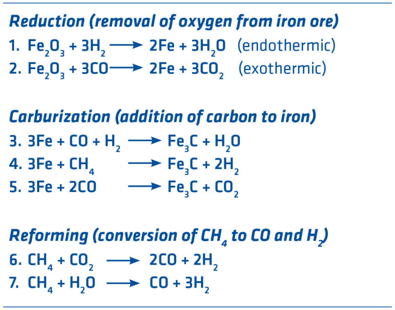
FIGURE 2.
Ironmaking Reactions
In the case of the standard MIDREX Process using natural gas (MIDREX NG), the typical gas content is 55 mol % H2 and 36 mol % CO with the balance comprised of H2O, CO2, N2, and CH4. Since reduction occurs between 800 and 900°C, temperature control is a very important consideration. Reaction 1 is endothermic (requires heat) while reaction 2 is exothermic (gives off heat). Reforming reactions are highly endothermic and mostly done in the reformer, although some in-situ reforming is taking place in the shaft furnace. The thermal balancing of Reactions 1 & 2 makes the MIDREX Process easy to control because the temperature in the furnace stays relatively constant. Since 1969, MIDREX Plants have produced more than 1 billion tons of DRI made with over 50% hydrogen.
Direct reduction with higher levels of hydrogen has been proven in a MIDREX Shaft Furnace. The FMO MIDREX Plant in Venezuela uses a steam reformer, and H2/CO has varied from 3.3 to 3.8. There are also six MIDREX Modules that utilize gas made from coal, and these have H2 to CO ratios from 0.37 to 2.0. Thus, the MIDREX Process has successfully produced DRI at H2/CO ratios from 0.37 to 3.8.
On a smaller scale, Midrex has vast experience with hydrogen reduction. In the late-1970s to mid-1980s, Midrex operated a pilot plant at its Research & Development Technology Center, which is shown in Figure 3. The pilot was built to test and demonstrate the Electrothermal Direct Reduction Process (EDR). While the purpose of this pilot plant was not to test hydrogen reduction, several campaigns utilized a very high hydrogen content – as high as 4.2 H2/CO in 1986.
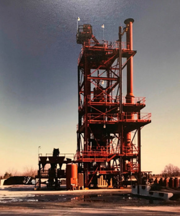
FIGURE 3.
Multi-purpose Pilot Plant at Midrex R&D Technology Center circa 1990.
MIDREX HYDROGEN IRONMAKING
Steelmakers – especially European steelmakers – face a daunting challenge in transitioning to near carbon-free ironmaking. Traditional operation of blast furnace/basic oxygen furnace (BF-BOF) steel mills is unlikely to meet the target CO2 reductions in the Paris Agreement of 2016, and BFs are generally old and need expensive relines. EAFs will need significant amounts of ore-based metallics (pig iron and DRI/HBI) to dilute the residuals in scrap. Pig iron production is predominantly BF-based and there is but one DRI plant currently operating in the European Union (EU), ArcelorMittal Hamburg. Hydrogen is not available in the quantities nor the cost needed to be competitive, and no one can predict when it will be.
However, the same basic process technology that is in use by ArcelorMittal Hamburg – MIDREX NG – is the first step in the Midrex transition to 100% hydrogen ironmaking. MIDREX NG already uses significant amounts of hydrogen in its reducing gas and can cut CO2 emissions by 35% compared to the coke oven/ blast furnace (CO/BF) ironmaking route. For a typical MIDREX NG plant, up to 30% of the natural gas input to the plant can be replaced with hydrogen without any changes to the process equipment. Operation with higher percentages of hydrogen is achievable with low-risk equipment modifications.
Therefore, a MIDREX NG plant operating with 100% natural gas could be built now, while the availability of hydrogen in sufficient quantities and at a competitive cost is being developed, and later transitioned to use up to 100% hydrogen.
Midrex can design greenfield plants based on MIDREX H2 technology specifically for 100% hydrogen operation or for majority hydrogen operation with minimal natural gas usage. Hydrogen for a MIDREX NG with H2 addition or MIDREX H2 plant can be obtained from various sources including carbon capture (see later in this article).
MIDREX NG WITH H2 ADDITION
A MIDREX NG plant can be equipped to operate with H2 substituted for some or most of the natural gas normally utilized by the plant. This evolutionary plant technology provides the flexibility to replace any percentage of the natural gas (NG) feedstock with H2 based on the plant’s operating goals. This provides the flexibility the plant needs to respond to ever changing market needs and feedstock availability. The flowsheet shown in Figure 4 indicates the three H2 injection points when utilizing MIDREX NG with H2 addition. Any existing MIDREX NG plant can be easily converted for hydrogen addition.
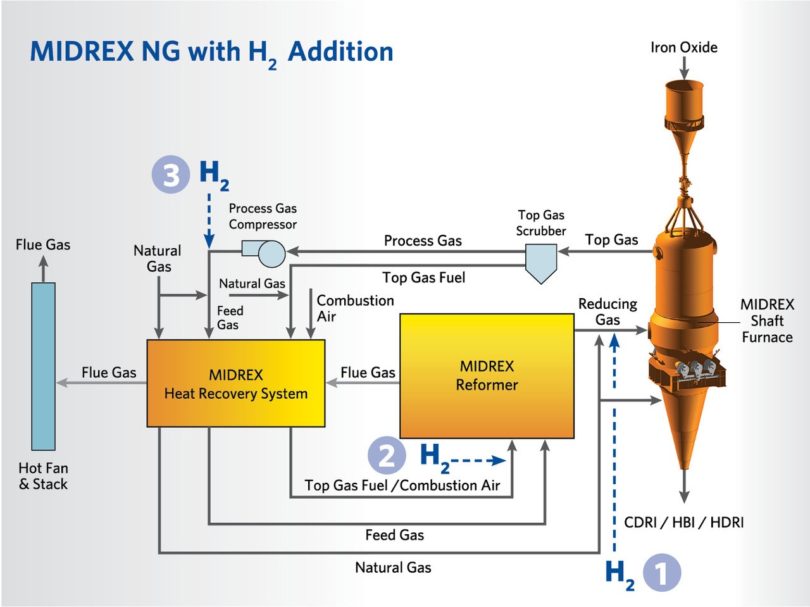
FIGURE 4.
H2 Injection Points Based on Percentage of NG Replaced by H2
Table I indicates the H2 injection point and when it is used based on the percentage of NG replaced by H2.
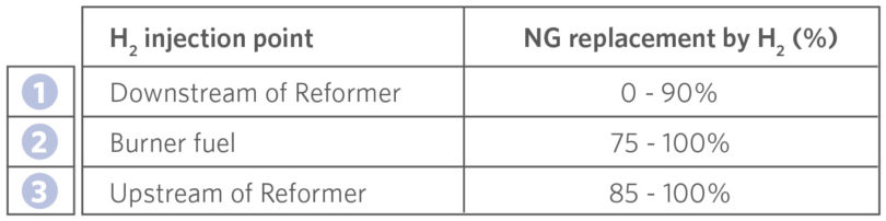
TABLE I.
H2 Injection Point Based on Percentage of NG Replaced by H2
In the early stages of H2 transition, the small amount of H2 added is injected downstream of the reformer without preheating. From 0-75% NG replacement, the hydrogen is only utilized in the process downstream of the MIDREX Reformer.
This facilitates optimizing reformer operation so it can be held as close to the MIDREX NG operating conditions as possible during H2 transition while maximizing the reducing gas quality to the reduction furnace. In order to maintain the DRI product carbon as far into the replacement as possible and still continue to reduce the carbon footprint, when the NG replacement percentage reaches ~75%, H2 is added to the reformer burners. H2 injection is introduced upstream of the MIDREX Reformer between ~85-100% NG replacement to maintain reducing gas quality and enhance energy efficiency in the process.
CONVERSION TO MIDREX NG WITH H2 ADDITION – PHILOSOPHY
The Midrex philosophy for converting from MIDREX NG to MIDREX NG with H2 addition is as follows:
- Maintain full plant capacity across the full transition range.
- Maximize the DRI carbon at each point across the full transition range.
- Maintain optimum reducing gas quality >9.5 to the reduction furnace can be achieved with H2 addition downstream of the reformer up to 80% NG replacement by H2. Above 80% NG replacement, the H2 addition is transitioned to the feed gas side of the reformer.
- Apply the standard type of centrifugal compressors used by Midrex (with the addition of a 3rd stage of compression for higher NG replacement >80%).
- Maintain the required amount of thermal mass flow to support the increasing endothermic reduction load. Higher H2 endothermic reduction load in the furnace requires a larger thermal mass flow at the bustle since the H2/CO increases as H2 addition increases (See Figure 5). The bustle gas flow per ton is increased steadily over the transition to 100% H2, as the H2/CO ratio rises to infinity.
- Minimize equipment modifications or the addition of new equipment to the plant.
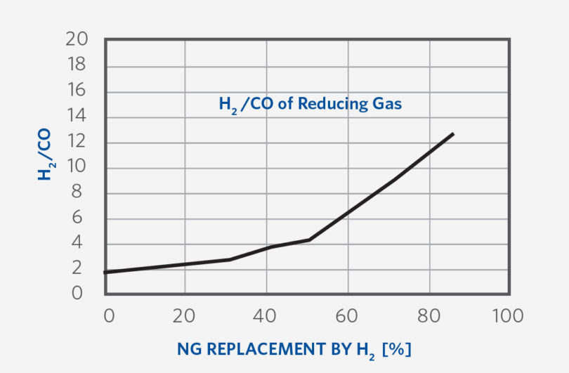
FIGURE 5.
H2/CO Trend of Reducing Gas
CONVERSION TO MIDREX NG WITH H2 ADDITION - EQUIPMENT
An existing MIDREX NG plant requires very little equipment modification to be converted to MIDREX NG with H2 addition. No equipment modifications are required to the feed/discharge systems, reduction furnace, scrubbers, process piping, reformer, oxygen injection systems, carburizing gas injection systems, product cooler, and HBI cooling systems. This section describes the major plant areas that need to be considered and modified to accommodate the full range of operation from 100% NG to 100% H2.
1. Process gas compressors
Increasing addition of H2 to the loop requires that the total process gas flowrate needs to increase. The increasing flow is driven by the fact that reduction by hydrogen is more endothermic than reduction by CO. The higher process gas flowrate is needed to maintain the energy balance (thermal mass) in the shaft furnace. For an existing plant, the process gas compressor capacity will become limiting at about 30% NG replacement. The addition of a single additional compression stage allows for operation across the full transition range.
2. Heat Recovery Area
The heat transfer load on the heat recovery system decreases as H2 addition increases. In order to maintain high energy efficiency and operational flexibility, some modifications are needed for the heat recovery system. For example, additional piping and valving adds the ability to control and balance the performance of the heat recovery bundles, which along with some minor equipment additions allows the system to operate across the full range of the transition.
3. Cooling Gas Compressor Area
If the MIDREX NG Plant is designed to discharge CDRI (cold DRI) either directly from the reduction furnace or through an external product cooler at NG replacement levels > ~70%, an additional small parallel compression step needs to be installed. As the NG replacement progresses and NG is withdrawn from the cooling zone, the gas composition reverts to mostly N2 or a mixture of H2 and N2, which drives the cooling gas requirement from 650 Nm3/t-DRI up to as much as 1,000-1,100 Nm3/t-DRI.
4. Process Water Areas
The load of cold process water and hot process water changes as H2 addition increases. Figure 6 indicates one example of this water flow trend with NG replacement. To take advantage of this reduction in hot water demand and increase in cold water demand, the installation of piping and valves to support this operational change need to be made. Additionally, more cooling tower capacity, recirculation and supply pumps with interconnecting piping for the higher H2 operation are required to support the higher condensation and cooling loads on these systems.
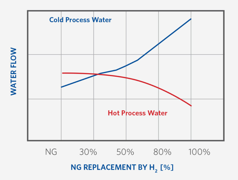
FIGURE 6.
Cold and Hot Process Water Flow during H2 Transition
EFFECT ON PLANT OPERATION AND DRI CARBON
DRI carbon is derived from the NG consumed in a MIDREX Plant. Maintaining carbon in HDRI (hot DRI) is possible across most of the range from 0-100% H2 within specified limitations. As the transition to 100% NG replacement progresses, maintaining higher percent product carbon is not possible. For example, HDRI carbon would be ~1.5-2.0% in the case of 30% NG replacement and ~1.3-1.5% in case of 75-85% NG replacement (See Figure 7).
Though carbon in CDRI is higher than in HDRI since carbon loss occurs at the hot transport conveyor, this drop in carbon content is directly related to the removal of carbon atoms from the process by NG replacement. Operation of the process and the priority given to which NG users are replaced first is optimized to retain as much carbon in the HDRI as possible for as long into the transition as possible.
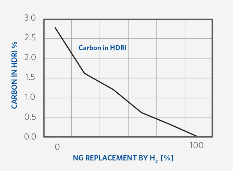
FIGURE 7.
Carbon in the DRI as H2 Replacement increases
CARBON CAPTURE, UTILIZATION & STORAGE (CCUS)
CO2 removal is not necessary in a MIDREX NG plant or a MIDREX NG with H2 addition plant because the CO2 is recycled back into the reformer and converted into CO – a kind of carbon loop. However, it is possible to include a CO2 removal system in these plants if it is economical (e.g. carbon tax credits) and if there is a means to store or utilize the CO2. Additionally, Midrex has engineered CO2 removal systems for plants based on coal gasification – which is required for the process – that can take advantage of carbon capture and storage (CCS).
There are two options to separate CO2 and capture it:
- Remove CO2 from the top gas fuel, which is used in the reformer for heating. CO2 emissions can be reduced by 0.25 to 0.35 t/t DRI.
- Remove CO2 from the flue gas of the reformer, after heat recovery. CO2 emissions can be reduced by ~0.5 t/t DRI (for a 2.0 million t/y plant, that means an additional 500,000 to 1,000,000 t/y of CO2).
The two options can be used together. Each option removes about half of the CO2 being emitted, making it is possible to achieve near zero CO2 emissions. Any MIDREX Plant can be built with CO2 removal or provisions to install CO2 removal at a later date, when the economics are more favorable.
CONCLUSION
Iron and steelmaking are a large contributor to the emission of greenhouse gases, notably CO2. The industry is facing increasing pressure to decarbonize, but there are many challenges to overcome. Hydrogen ironmaking is a real possibility for future (near) carbon-free steelmaking, but there are significant uncertainties around the availability of hydrogen in volumes needed for ironmaking and at a competitive cost.
The best possibility for reducing the steel industry’s CO2 footprint is the use of hydrogen as an energy source and reductant for iron ore in the MIDREX Process. Today, reduction of CO2 emissions by 50% (over BF/BOF) is achievable and well proven. Although the hydrogen comes from natural gas (‘blue hydrogen’),the process is flexible enough to accept ‘green’ hydrogen produced from water electrolysis as it becomes available and economical, which will further reduce CO2 emissions.
Midrex offers technologies that bridge the transition from 100% natural gas to 100% hydrogen direct reduction: MIDREX NG, for the immediate and mid-term future allowing up to 30% natural gas replacement with hydrogen without equipment modifications, MIDREX NG with H2 addition, which provides a plant the flexibility to operate on any mixture of natural gas and hydrogen (up to 100% hydrogen) with some low-risk modifications, and MIDREX H2, which is designed to use up to 100% hydrogen in a MIDREX Shaft Furnace as the feed gas. All MIDREX Process configurations can operate on the industry’s broadest range of raw materials and reducing gas sources including hydrogen from carbon capture, utilization, and storage (CCUS).
Ultimately, MIDREX H2 holds great promise for advancing the decarbonization of ironmaking leading to near zero-emission steelmaking. However, investments for the future can be made today in plants based on MIDREX NG technology, knowing they are readily adaptable as we advance toward the Hydrogen Economy.
References:
- Bell, Terence. “The History of Steel.” ThoughtCo, Aug. 28, 2020, thoughtco.com/steel-history-2340172.
- Hites, Becky E. “The Growth of EAF Steelmaking.” Recycling Today, April 30, 2020.
- IEA (2020), Iron and Steel, IEA, Paris https://www.iea.org/reports/iron-and-steel
- https://www.globalefficiencyintel.com/new-blog/2021/global-steel-industrys-ghg-emissions
Related Reading
 Mar 25, 2026
 Feb 04, 2026