
“It All Started in Portland…” 50 Years Ago

John KopfleRetired
Articles by John
Frank GriscomDirect From Midrex Editor (1981-93) and Consultant/Contributor (2013-25)
Articles by Frank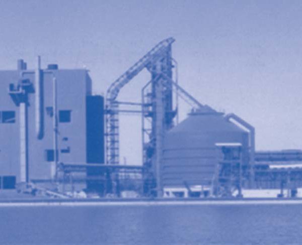
AUTHORS’ NOTE
The cover of the 3rd quarter 1989 issue of Direct From Midrex was a departure from the normal silver-gray color and a bright red band across the bottom right-hand corner identified it as a special MIDREX® DR Technology issue commemorating 20 years of commercial operation. The first article carried the headline, “It All Started in Portland …” in recognition of the start-up of the first commercial MIDREX Direct Reduction Plant in May 1969, at Oregon Steel Mills in Portland, Oregon, USA. Now, fast-forward 30 years – the Direct From Midrex cover design has changed a couple of times and DFM now is published on the Midrex website rather than printed, but the plant in Portland is still celebrated for its role in launching the world’s most successful, widely used direct reduction process. Midrex teammates celebrated the Portland start-up on May 17, exactly 50 years to the day and hour (see News & Views). We now invite you to join us for a journey through the first 50 years of inspiration, innovations, and improvements that are MIDREX Direct Reduction Technology.
A BETTER MOUSETRAP: American poet, Ralph Waldo Emerson, is credited with the phrase, “Build a better mousetrap, and the world will beat a path to your door.”
This may have occurred to Donald Beggs on a Saturday afternoon in the mid-1960s, as he was cutting the grass at his home. Beggs, who managed the research group of Midland-Ross Corporation’s Surface Combustion Division in Toledo, Ohio, USA, was intrigued by the idea of reforming natural gas to produce a high-quality synthesis gas that could be used to reduce iron oxide pellets. Surface Combustion was known for its combustion and heat transfer knowledge, its proprietary designs for a near-stoichiometric gas reformer, and a gravity-flow shaft furnace for indurating iron oxide pellets. Beggs and Jack Scarlett, another member of the Surface Combustion Research Group, developed a process flowsheet and proposed building a pilot plant in Toledo. The plant, with an hourly production capacity of 180-225 kilograms, was built and operated successfully in 1967. The direct reduced iron (DRI) it produced was supplied to Oregon Steel Mills (OSM) in Portland, Oregon, which operated an electric arc furnace (EAF). To the delight of everyone involved, OSM established a new production record using DRI. As a result, OSM contracted Midland-Ross to build a full-scale commercial protype plant in Portland. The plant, pictured in Figure 1, consisted of two modules, each with a 12-feet diameter (3.7-meters) shaft-type reduction furnace capable of producing 150,000 metric tons per year (t/y) of DRI. of DRI. Midland-Ross retained ownership of the plant and sold DRI to OSM on a long-term contract. Plant start-up was on May 9, 1969, and regular operations commenced on May 17, 1969.
The Midrex Division was formed that same year to develop the market potential of the MIDREX Direct Reduction Process. A patent for the MIDREX Process was granted to Beggs et. al. on July 24, 1973 (Figure 2).
THE PATH LESS TRAVELED
Conventional wisdom in 1968 was to use a steam reformer (with a large excess of steam as reactant) to produce reducing gas because it had been used in various industries for half a century. Also, it was believed that stoichiometric reforming (low excess steam) would cause severe catalyst degradation.
Beggs and his group knew that to produce a good quality reducing gas in a steam reformer, the reformed gas would have to be quenched to remove excess steam and then re heated to reduction temperature. Surface Combustion had been using stoichiometric reforming for 20 years and was manufacturing a gas generator that reacted natural gas and air at near stoichiometric ratio to produce a car burizing gas, which was mostly H2, N2, and CO with small amounts of CO2 and H2O. Therefore, Beggs and his group were confident that a near-stoichiometric (“Midrex stoichiometric”) reformer operating at low pressure and capable of reforming CO2 and H2O would be successful in a DRI plant and simpler than using steam reforming.
They were correct. The MIDREX Reformer produces a high-quality reducing gas without excess steam that can be fed directly into the reduction furnace without the need for quenching and reheating. The ability to use CO2 and H2O to reform CH4 allows for 2/3 of the top gas from the reduction furnace to be recycled to the reformer, where it is mixed with fresh natural gas to produce a carbon monoxide (CO) and hydrogen (H2)-rich reducing gas.
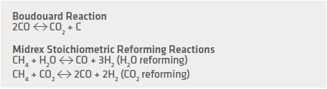
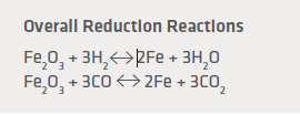
Because the Surface Combustion gas generators were simple devices, they were designed without natural gas desulfurization. As a result, the pilot reformer and the first commercial reformer used in the Portland plant were designed to operate with the small amount of sulfur (2-5 ppmv) contained in the natural gas. This sulfur carried into the feed gas and slowed the Boudouard carbon-forming reaction – a practice used today in MIDREX Plants to improve catalyst performance and to prolong catalyst life.
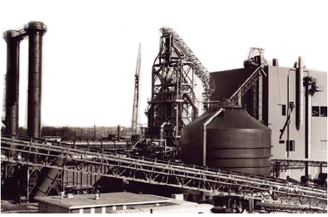
FIGURE 1. First Commercial MIDREX Plant at Oregon Steel Mills (OSM)
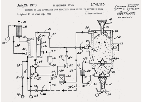
FIGURE 2. Original MIDREX Process Patent
The forward-thinking, modular design of the MIDREX Reformer (Figure 3) has been instrumental in the annual rated capacity of MIDREX Modules increasing from 150,000 tons in 1969 to 2.5 million tons today*. The simple, mild steel construction of the reformer allows for local fabrication in small, modular units that can be easily transported and erected at the plant site.
The beginnings of modern catalyst design and loading profiles emerged from the pilot-scale re-former constructed in Toledo and were included in the first commercial plant at OSM. Initially, an inert material was used in the inlet section of the reformer tubes (at the bottom), with an active catalyst in the middle and on top. This was done to heat the gas quickly above the range of the carbon-forming reactions. An innovation developed by Surface Combustion was to preheat the process gas before it entered the reformer tubes. This allowed the pre-heat (lower) section of the reformer tubes to be used for reforming. This discovery became the basis for the catalyst loading philosophies used today in MIDREX Plants, depending on local factors. As MIDREX Plants increased in numbers and capacities, larger quantities and more sophisticated catalyst materials were required. In the tradition of the Surface Combustion pioneers, Midrex has remained actively engaged in designing and testing the modern, high efficiency catalysts in use today (Figure 4).
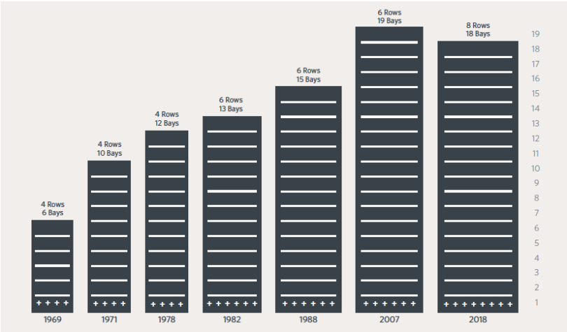
FIGURE 3.
Evolution of MIDREX Reformer Design
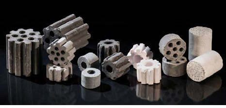
FIGURE 4.
Catalyst types used in MIDREX Plants
* AUTHOR’S NOTE: MIDREX Plants can include one or more modules. A MIDREX Module includes a shaft furnace, reformer, heat recovery system, and the ancillary systems and equipment to support their operation.
TAKING THE SHAFT FURNACE TO NEW HEIGHTS
 Innovation involves introducing new methods and ideas to something established to create a different (and usually better) way of doing things. There is no better description of what went into designing the reduction furnace for the MIDREX Direct Reduction Process. Midland-Ross was using a shaft-type indurating furnace for iron ore pelletizing in Cooley, Minnesota, USA, in the early 1960s. This furnace shape seemed ideal for what Beggs and his engineers had in mind – to create a process that would produce a higher value iron product than indurated oxide pellets.
Development of the MIDREX Shaft Furnace started with the Toledo pilot plant, which included a 1.3-feet (~0.4-meter) inside diameter (ID) reduction vessel. By the time of the Portland commercial plant in 1969, the size of the reduction furnace had increased to 12 feet (~3.7 meters) ID, with a rated capacity of 150,000 t/y. Over the next 20 years, the ID of the MIDREX Shaft Furnace grew progressively to 5.0 meters, then 5.5 meters, then 6.5 meters. Each size increase resulted in higher capacity so that by 1990, the OPCO Plant in Venezuela (now known as FMO) was rated at 1.0 million t/y. OPCO, the first MEGAMOD®, was built to serve the merchant market for HBI.
Today, a single-module MIDREX Plant, equipped with a 7.65-meters ID MIDREX Shaft Furnace, is capable of producing 2.5 million t/y of DRI products (SUPERME-GAMOD™ Furnace). This furnace has been commercialized at Tosyali Algerie Steel and a second one is being built at Algerian Qatari Steel (AQS).
As the diameter of the reduction furnace expanded, the height also was increased to maintain the desired flow characteristics and the speed of the reactions that occur in the furnace. The shaft furnaces in the Portland plant were 45-46 meters tall. Today, reduction furnaces in the two newest MIDREX Plants (Tosyali and AQS) measure 137.5 meters from DRI discharge feeder to oxide feed hopper (Figure 5).
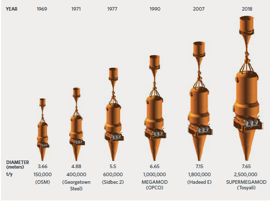
FIGURE 5.
Evolution of MIDREX Shaft Furnace Design
ADDING HEAT RECOVERY
With the low cost of natural gas at the time, the Portland plant did not include provisions for recovering heat, and first generation MIDREX Plants were designed to recover only a minimal amount of heat from the flue gas. However, as gas prices increased, the economics of heat recovery became much more favorable, especially with the associated benefits of increased reformer capacity. During the first decade of the MIDREX Process (1970-80), combustion air preheat was added and increased from 480° C to 650° C and reformer feed gas preheat was added and increased from 400° C to 540° C. Top gas preheat was introduced during the first half of the 1990s, with the cumulative effect of reducing natural gas consumption to 2.4 net Gcal/t of DRI.
The heat recovery system in the latest generation MIDREX Plant is comprised of a hot fan and six stages of heat exchangers (Figure 6). The hot fan pulls flue gas from the reformer through the heat exchangers and releases the spent gas through the stack into the atmosphere. This reduces overall energy consumption significantly and enhances environmental performance. The heat exchangers preheat the following gas streams: hot and cold combustion air and top gas fuel (reducing reformer energy consumption), hot and cold feed gas (reducing reformer energy consumption and increasing reforming capacity), and natural gas added to the reducing gas and the shaft furnace (reducing the temperature loss within the shaft furnace and facilitating better utilization of natural gas to deposit carbon on the DRI).
OPTIONS IN ENERGY
Although natural gas is the energy source most often cited in relation to MIDREX Direct Reduction Technology, it was not the first nor is it the only one. Surface Combustion in 1963 developed a process for reducing unfired pellets made from iron ore concentrate and coal fines in a rotary hearth furnace known as Heat Fast. The technical results from the Heat Fast DRI were good but analysis of the economics for producing hot metal showed no benefit versus the conventional blast furnace, and Surface Combustion turned its attention to natural gas-based direct reduction.
With proof of the MIDREX Process standard flowsheet (Figure 7) and the initial commercial successes during the 1970s, Midrex turned its attention to expanding the energy options for making DRI. Flowsheets were created to use with the leading coal gasification technologies of the time (Lurgi and Texaco), as well as options for using coke oven gas. Today, MIDREX Plants are operating with reducing gas produced by coal gasification (JSPL Angul) and with export gas from the COREX® Process (ArcelorMittal South Africa and JSW Toranagallu) in addition to traditional natural gas. The standard MIDREX NG (Natural Gas) flowsheet includes: a hot discharge furnace, with the flexibility to produce hot DRI (HDRI) and hot briquetted iron (HBI), as well as cold DRI (CDRI), a near-stoichiometric, catalytic reformer; and up to six stages of heat recovery.
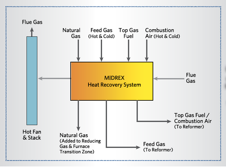
FIGURE 6.
MIDREX Heat Recovery System Diagram
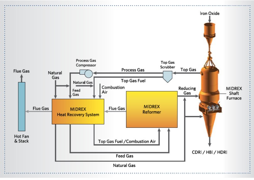
FIGURE 7.
MIDREX Process Standard Flowsheet
Midrex and Praxair, Inc. built and operated a demonstration plant in 2012-13 to prove the technical feasibility of the Thermal Reactor System (TRS), a means of producing reducing gas from coke oven by-product gas for making DRI.
In 2017, Midrex introduced a flowsheet for substituting hydrogen (H2) for up to 1/3 of the required natural gas in new or existing MIDREX Plants. For example, 60,000 Nm³/h of H2 can be substituted for approximately 20,000 Nm³/h of natural gas in a 2.0 million t/y plant.
Midrex also has a flowsheet for using almost pure hydrogen to make DRI in a MIDREX Shaft Furnace. The MIDREX H2™ flowsheet is similar to the standard MIDREX Process except that the hydrogen input gas is generated external to the process. Thus, there is no reformer and a heater is used to bring the gas to the required temperature. In practice, the reducing gas H2 content is about 90%, with the balance being CO, CO2, H2O, N2, and CH4.
NEW OWNER … NEW HORIZONS
By the late-1970s, MIDREX Plants were operating in North and South America, Europe, and the Middle East. Midrex Corporation was headquartered in Charlotte, North Carolina, USA, and German steel entrepreneur Willy Korf was its owner. Korf’s vision for the MIDREX Process was to provide the iron units for electric arc furnace (EAF)-based steel mills sized to local or regional needs. This “mini-mill,” as it became known would provide the impetus for industrial development and economic growth. Further to this thinking, Midrex instituted a technology licensing approach in which Midrex would design the plant and license the process technology for local or national owners to operate the plant and use or sell the DRI. Midrex would train the plant personnel and interact with them during the operating life of the plant to develop and integrate technology innovations and improvements. This two-way technology transfer practice was unique to Midrex at the time and has been instrumental in the company’s success to date. Global DRI production increased during the first decade of the MIDREX Process from less than 750,000 tons/year in 1970 to almost 7.5 million tons/year by 1980. The annual production of DRI by MIDREX Plants jumped from little more than 50,000 tons in 1970 to almost 4 million tons by 1980, accounting for more than 50% of worldwide DRI production in 1979. As Korf had sensed, EAF based mini-mills coupled with a DRI plant in natural gas-rich regions would become drivers of economic development. The allure of market-sized steel mills also was gaining traction in established markets, especially the USA. As the amount of “cold charge” (scrap steel vs. blast furnace hot metal) steel production increased, demands for scrap greatly increased and were reflected in the prices. Midrex responded to the increasing demand for DRI outside of locations where it was being produced by developing a form of DRI that would be strong enough to withstand the rigors of handling and shipping and safe from the risk of severe oxidation during ocean transport. Harking back to its innovative heritage, Midrex designed a hot discharge shaft reduction furnace in 1982 and matched it with a system for molding HDRI into a dense, compacted form known as hot briquetted iron (HBI). The first MIDREX Plant designed to produce HBI was started up on Labuan Island, Malaysia, in 1984 (Figure 8), and continues to produce and sell HBI throughout the Asian region to this day.

FIGURE 8.
First MIDREX HBI Plant on Labuan Island, Malaysia
KOBE STEEL – OWNER AND PARTNER
![]() As early as the first MIDREX Plant at Qatar Steel Company (QASCO), Kobe Steel Ltd. has been actively involved with the MIDREX Process. Kobe Steel was part of a joint venture with the State of Qatar to build an EAF steel mill coupled with a DRI plant as part of a well-conceived industrialization program to utilize the nation’s massive natural gas reserves. Following a successful feasibility study in 1974, Midrex was selected as the DRI technology supplier because of the adaptability of the MIDREX Process to extreme climatic conditions and excellent worldwide plant performance record. The MIDREX Plant was started up in August 1978, as the first DRI facility in the Middle East.
As early as the first MIDREX Plant at Qatar Steel Company (QASCO), Kobe Steel Ltd. has been actively involved with the MIDREX Process. Kobe Steel was part of a joint venture with the State of Qatar to build an EAF steel mill coupled with a DRI plant as part of a well-conceived industrialization program to utilize the nation’s massive natural gas reserves. Following a successful feasibility study in 1974, Midrex was selected as the DRI technology supplier because of the adaptability of the MIDREX Process to extreme climatic conditions and excellent worldwide plant performance record. The MIDREX Plant was started up in August 1978, as the first DRI facility in the Middle East.
The continued strong performance of MIDREX Plants and the signing of close to a dozen contracts for new plants led KSL to acquire the assets of Midrex Corporation from Korf in August 1983. A KSL spokesman at the time said, “the combining of the DRI expertise of Midrex and Kobe Steel know-how in the area of steel mill construction and operation is expected to prove beneficial to both organizations and their clients.”
With the backing of Kobe Steel, Midrex has renewed the commitment to innovation and continuous improvement on which it was founded. The Midrex business model is built on the concept of renewable technology – a self-sustaining cycle that blends science, engineering, marketing, and real-world experience to identify business opportunities and transform them into sustainable solutions (Figure 9).
In 2015, the Midrex Research & Development Technology Center, located in Pineville, NC, near the Midrex headquarters in Charlotte, NC, was significantly expanded and modernized to better serve the changing demands of the global steel and minerals processing industries. The R&D Technology Center is now the principal facility for ferrous and non-ferrous reduction technology development for both Midrex and Kobe Steel. Capabilities of the R&D Technology Center include: physical testing of raw materials; lab-scale and bench-scale testing and evaluation of catalysts, reductants, iron ores, and DRI; and commercial-scale testing and evaluation of mineral chemistries, minerals preparation, pelletizing, briquetting, and melting.
Since joining the Kobe Steel Group, the installed capacity of MIDREX Plants has increased more than ten-fold and MIDREX Plants have produced more than 60% of the world’s annual supply of DRI products for more than 30 years (Figure 10). In June 2018, the cumulative total of DRI products produced by MIDREX Plants exceeded 1 billion tons.
FIGURE 9. MIDREX Technology Cycle
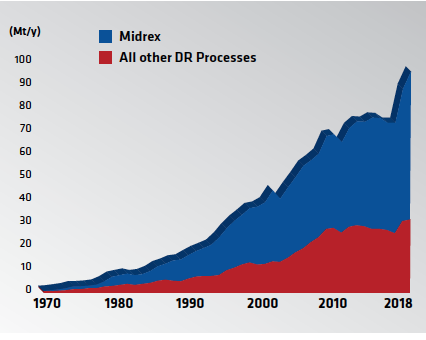
FIGURE 10.
Global DRI Production Since 1970
DESIGNED FOR TODAY, ENGINEERED FOR TOMORROW®
It has been a long and challenging journey from those early “trial and error” days in Portland to the confidence of starting up the world’s most reliable, adaptable, and productive DRI plants. Along the way, Midrex has advanced the state-of-the-art in direct reduction technology with many innovations and improvements and numerous performance achievements (see sidebar). Its advocacy for the benefits of using DRI products, especially when used in combination with scrap in the EAF, is widely credited with developing and expanding the DRI market.
“Designed for Today, Engineered for Tomorrow” is more than a marketing slogan. It represents the basic philosophy that has guided Midrex for 50 successful years – to provide products and services that are responsive to the current wants and needs of iron and steel producers and conducive to innovation and improvement for the future.
Like a fine wine, Midrex produces “no technology before its time”; and when it does, you can be assured that it is relevant, reliable, and results-driven. Midrex enters the next 50 years of the MIDREX Process with the same spirit of innovation and determination that drove the Surface Combustion pioneers.
Related Reading
 Jun 29, 2021
 Jun 30, 2020