
Fueling the Future of Ironmaking: MIDREX Flex™

Geoff WallworkGlobal Solutions Principal Engineer
Articles by Geoff
INTRODUCTION
According to the International Energy Agency (IEA), the industrial sector is responsible for 23% of global energy-related CO2 emissions, and iron and steel accounts for 30% of the sector’s total (Figure 1). That is 2.6 giga-tons of CO2 annually. To realize the long-term transformational change envisioned by the IEA, the CO2 intensity of crude steel needs to fall an average of 2.5% annually between 2018 and 2030.
To meet the demands and climate goals of IEA’s net-zero emissions (NZE) scenario, the iron and steel industry must decrease its CO2 emissions by at least 50% by the year 2050. Achieving this reduction will not be easy and presents a challenge to the industry.
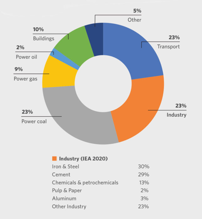
FIGURE 1.
Global Energy-Related CO2 Emissions by Sector
Short term reductions in CO2 emissions in recent years have come largely from energy efficiency improvements; however, opportunities for further efficiency improvements will likely soon be exhausted. Thus, innovation to commercialize new low-emissions process routes utilizing hydrogen and carbon capture, utilization, and storage (CCUS) in the upcoming decade will be crucial to realizing the long-term decarbonization goals.
Emerging technologies making use of CCUS are expected to cut emissions mainly after 2030 (see Table 1). Recently, there has been significant progress in 100% electrolytic hydrogen-based DRI steelmaking (e.g., H2 Green Steel’s DRI-EAF steel mill project in Boden, Sweden), which is forecasted to account for nearly half of iron-based steel production by 2050 in IEA’s 2023 NZE Scenario.
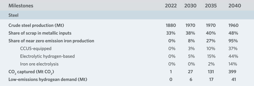
TABLE 1.
Emissions reductions from steel production is challenging due to a heavy reliance on fossil fuels today, process emissions from incumbent routes, and high trade exposure. Increased scrap recycling and mass deployment of innovative technologies are key levers for reducing emissions.
WHAT IS MIDREX DOING TO SOLVE THE CHALLENGE?
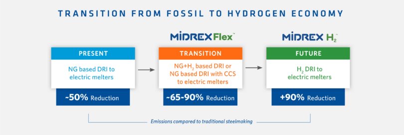
The standard natural gas-based configuration of the MIDREX® Process is the most widely used technology to produce all forms of direct reduced iron (DRI) products and is seen as the most viable near-term response to reduce CO2 emissions. Steel production via the direct reduced iron-electric arc furnace (DRI- EAF) route already generates 50% less CO2 emissions compared to the blast furnace (BF)-basic oxygen furnace (BOF) method.
As decarburization is key to the sustainability of the steel industry, and ironmaking represents the majority of CO2 emissions in steelmaking, DRI technology must lead the way.
The ultimate method for reducing the steel industry’s CO2 footprint is to use 100% hydrogen as the reductant to make DRI in a MIDREX Shaft Furnace. This technology is known as MIDREX H2TM, which includes a specially developed electric heater in place of the MIDREX Reformer and reduces CO2 emissions up to 90% versus BF ironmaking.
However, Midrex offers another solution that allows steelmakers to adapt to the hydrogen economy at their own pace, which we call MIDREX FlexTM. This technology approach allows for the replacement of any percentage of the natural gas feedstock with hydrogen based on the plant’s operating goals and provides the flexibility for the plant to respond to ever-changing market needs and feedstock availability. Therefore, as sufficient quantities of hydrogen become available at competitive prices, a standard MIDREX Plant can be easily modified to operate with up to 100% replacement of the natural gas.
Although the MIDREX Reformer does a good job in converting recycled CO2 into carbon monoxide (CO) in the standard process flowsheet, a MIDREX Plant can be designed with a CO2 removal system if it is economical (such as for carbon tax credits) or if there is a means to store or utilize the captured CO2. These systems are typically designed to remove CO2 from the top gas fuel or the reformer flue gas.
GETTING TO KNOW MIDREX FLEX
Existing natural gas-based MIDREX Plants already have significant percentages of hydrogen in the reducing gas, with a typical hydrogen to carbon monoxide (H2/CO) ratio of 1.5 corresponding to approximately 55% H2 and 36% CO. So, MIDREX Flex technology can be considered an “evolutionary innovation,” as operation of a MIDREX Shaft Furnace with high levels of hydrogen has been proven successfully for decades. For example, the FMO plant in Venezuela has operated with H2/CO ratios as high as 3.8.
Let’s look at key aspects of MIDREX Flex (see Figure 2):
- Hydrogen Ready – Use up to 100% H2 as the reductant. Midrex has solutions ready to accommodate the entire range of input gas compositions at new and existing facilities.
- MIDREX Reformer – Ensures optimum reducing gas conditions throughout the entire range of the transition.
- MIDREX Shaft Furnace – Delivers consistent product quality throughout the transition. The influence of endothermic hydrogen reduction is mitigated by the reformer and uniform burden movement.
- Carbon Capture & Storage – Carbon capture and storage can be applied to several different process streams, from 50% to nearly 100%. Available for addition to existing facilities or new installations.
A plant utilizing the natural gas-based MIDREX Process can be transitioned to accommodate up to 100% hydrogen as the reductant with the MIDREX Flex configuration. No fundamental design changes are required for the MIDREX Reformer or the MIDREX Shaft Furnace. Additionally, a CO2 removal system can be applied to capture the CO2 for storage or utilization.
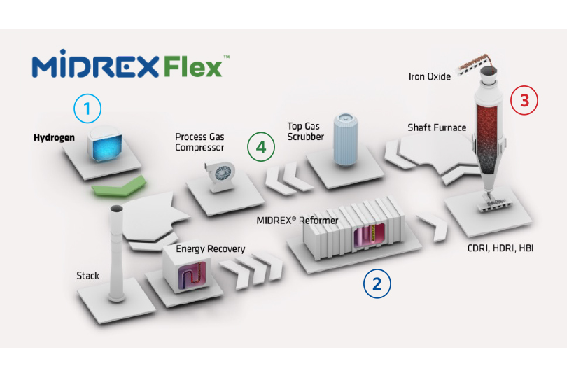
FIGURE 2.
MIDREX Flex
Operational Targets
There are several key operational targets during the transition to hydrogen with MIDREX Flex.
- The full plant capacity is maintained across the entire transition range while minimizing the requirement for equipment modifications or the addition of new equipment to the plant.
- The DRI product carbon is maximized at each point across the full transition range. Generally, this is accomplished by maintaining the transition zone natural gas flow as far into the hydrogen transition as possible.
- Optimum reducing gas quality to the MIDREX Shaft Furnace is maintained by maximizing the hydrogen addition downstream of the reformer.
The required amount of thermal mass flow to support the higher endothermic reduction load in the MIDREX Shaft Furnace is maintained across the entire transition range. The H2/CO ratio increases as the hydrogen addition increases, which requires a larger mass flow at the bustle.
Injection Points
Generally, minimal changes to the process flowsheet are required for operation with up to 30% replacement of the natural gas by hydrogen. For 100% replacement of the natural gas, additional equipment may be required, but the core equipment is suitable for the transition.
In the initial stages of the transition to hydrogen, a small amount of hydrogen is injected downstream of the reformer without preheating, shown as #1 in Figure 3. Injecting hydrogen at this location allows optimization of the reformer operation so it can be held as close to the standard operating conditions as possible during the transition while maximizing the reducing gas quality to the MIDREX Shaft Furnace. The maximum amount of hydrogen that can be injected downstream of the reformer will be based on the availability of oxygen injection or if preheating the hydrogen is available. Maintaining adequate reducing gas temperatures to the MIDREX Shaft Furnace is critical when injecting hydrogen in this location.
After maximizing the amount of hydrogen injected down- stream of the reformer, hydrogen can be added to the reformer burners to maintain the DRI product carbon as far into the replacement as possible and to continue reducing the carbon footprint. This is shown as #2 in Figure 3. Hydrogen injection can also be introduced upstream of the MIDREX Reformer to maintain reducing gas quality and enhance energy efficiency in the process. This is shown as #3 in Figure 3.
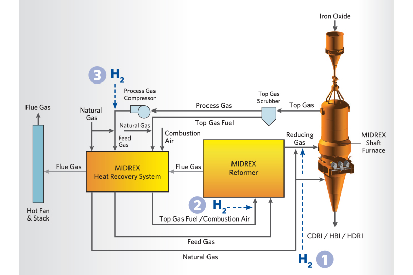
FIGURE 3.
H2 Injection Points
Typical Consumptions/Emissions
Table 2 provides the typical consumption and CO2 emissions for the transition from 100% natural gas to 100% hydrogen. As the hydrogen addition is increased, the natural gas consumption decreases, the H2/CO ratio increases, and the CO2 emissions decrease. At 100% hydrogen operation, the natural gas consumption and CO2 emissions are zero if the heater burners are fueled by hydrogen.
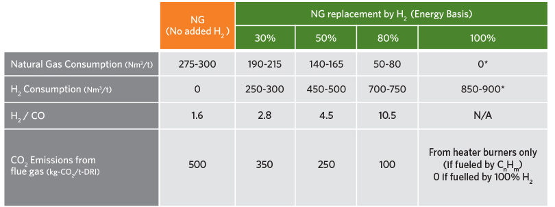
TABLE 2.
Typical Consumptions/Emissions
Operational Changes
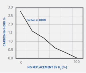
There are several operational changes to be expected during the transition to hydrogen with MIDREX Flex. As CO2 emissions and DRI product carbon are derived from the consumption of natural gas, both the CO2 emissions and the DRI product carbon will decrease as the natural gas is replaced with hydrogen.
As the hydrogen addition is increased, the H2/CO ratio will naturally increase as well. Also, the molecular weight of the process gas and reducing gas will decrease due to the relatively lighter weight of the hydrogen.
As mentioned previously, the amount of reducing gas flow must increase to maintain the energy balance in the shaft furnace.
And finally, there will be an increase in the demand for cold water and a corresponding decrease in the demand for hot water.
PLANT MODIFICATIONS
To convert an existing natural gas-based plant to MIDREX Flex requires minimal equipment modifications. Generally, hydrogen replacement of up to 30% of the natural gas, based on the original design capacity of the plant, requires no changes to the major process equipment including the shaft furnace and the reformer.
For natural gas replacement beyond 30% and to accommodate the full range of operation up to 100% hydrogen, some major plant areas will likely require modifications. These areas include the process gas compressors, heat recovery system, cooling gas compressor, and process water system.
Shaft Furnace
The shaft furnace for existing plants requires no fundamental changes across the full range of hydrogen addition. Reduction kinetics actually improve with higher amounts of hydrogen.
Increasing the hydrogen will increase the endothermic load in the furnace. The reduction furnace is an adiabatic reactor, so more heat input is required to sustain the reduction process with higher amounts of hydrogen.
There are two methods to increase the heat input:
- Increase the sensible energy entering the reduction furnace by raising the reducing gas temperature.
- Increase the total energy (or thermal mass) into the reduction furnace by raising the reducing gas flow per ton entering the bustle at any given temperature.
Raising the reducing gas temperature is the simplest method but oftentimes, the ore cannot be elevated to sufficient temperature to provide all the required additional reduction energy. The higher temperature required would cause the ore to become sticky and adversely affect material flow and productivity in the furnace. Acceptable top gas and bustle gas temperatures can be maintained by increasing the amount of reducing gas flow per ton entering the shaft furnace to provide the required energy for reduction.
Reformer
No fundamental design changes are required for the reformer. As the reformer for a standard natural gas-based plant is designed to operate on 100% natural gas, this design criteria provides the highest duty for the reformer operation. As the natural gas is replaced with hydrogen, the reforming overall heat load will decrease. As the amount of hydrogen increases, the amount of reforming required decreases and the reaction heat decreases. As the hydrogen replacement progresses to 100%, the reformer essentially becomes a heater to provide the necessary sensible heat to increase the temperature of the reducing gas.
The existing reformer catalyst is suitable throughout the transition. At 100% hydrogen operation, the existing catalyst can be substituted with inert catalyst since there is no reforming and only sensible heat transfer is necessary.
The reformer burners are designed to operate on top gas fuel, which has a heating value similar to hydrogen. The existing burners are suitable for the transition to hydrogen with only minor modifications.
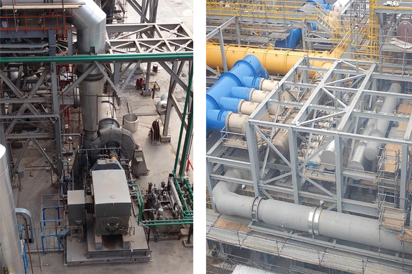
Shaft Furnace (left) & Reformer (right)
Process Gas Compressors
Since the natural gas is being replaced with hydrogen, process gas flow will need to increase to supply more thermal mass flow to the furnace. In general, the process gas compressor capacity will become a limiting factor at approximately 30% replacement of the natural gas. The addition of a single additional compression stage will allow for operation across the full transition range.
Heat Recovery
During the transition to hydrogen, the overall reformer heat load will decrease. Therefore, flows of flue gas, combustion air, and top gas fuel will ultimately decrease and the heat transfer will need to be reviewed for the heat recovery system.
If there is an existing top gas fuel heat recovery bundle, it can be repurposed for preheating the hydrogen to allow for more hydrogen to be injected downstream of the reformer as the transition progresses to higher amounts of hydrogen replacement.
Process Gas Compressors (left) & Heat Recovery (right)
Cooling Gas Compressor
For existing plants that produce cold DRI (CDRI), the cooling gas compressor will need to be evaluated for the transition to hydrogen. As the transition progresses, natural gas is withdrawn from the cooling zone loop. As a result, the cooling gas composition reverts from a mixture of methane and nitrogen to a mixture of hydrogen and nitrogen. This change in the cooling gas composition will increase the cooling gas flow requirement.
In general, it is expected that the cooling gas compressor capacity will become limiting at approximately 70% replacement of the natural gas.
Process Water System
Several changes associated with the transition from natural gas to hydrogen will occur within the process water system. More capacity may be required including such equipment as an additional cooling tower cell, recirculation pumps, and supply pumps.
Increasing the level of hydrogen in the reducing gas will increase the amount of water vapor in the top gas as a product of the reduction occurring in the furnace. This translates to a higher condensation heat load in the top gas scrubber and requires increased water flow to the packing and will create more water for the overall system to handle.
The cold process water demand will increase. On the other hand, the hot process water demand will decrease since the controlled process gas temperature at the exit of the top gas scrubber decreases as the hydrogen addition increases.
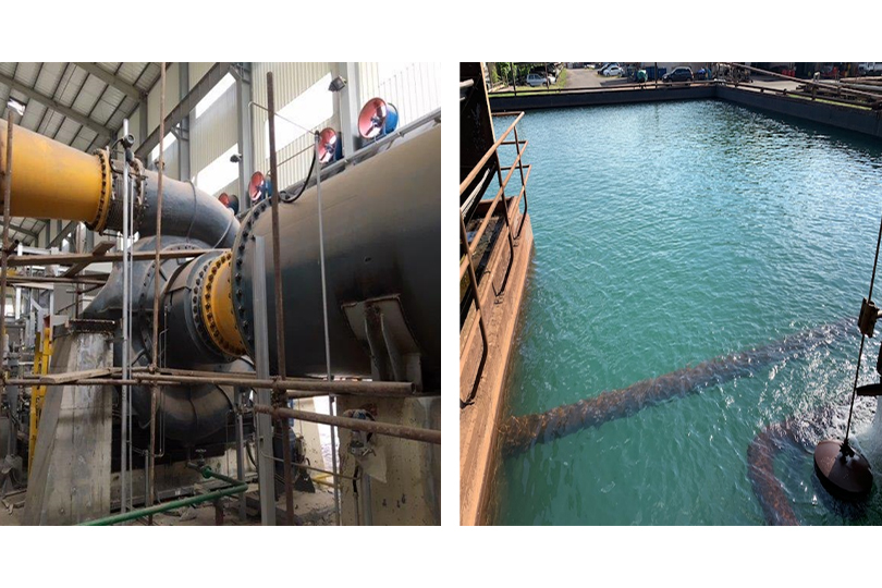
Cooling Gas Compressor (left) & Process Water System (right)
EVALUATION OF DRI REDUCED WITH HYDROGEN
Tests were conducted at the Midrex Research & Development Technology Center to compare some of the physical and chemical properties of DRI made with hydrogen versus reformed natural gas.
Table 3 shows the various iron oxides used for the evaluation. It included both lump and pellet oxides with various total iron contents.
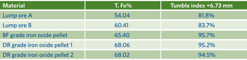
TABLE 3.
Typical Consumptions/Emissions
Reducibility Evaluation
The Linder Test was used to evaluate the reducibility of the oxides according to ISO-11257:
- Reformed NG Condition – 36% CO, 5% CO2, 55% H2, 4% CH4
- H2 Condition – 100% H2
- 760°C for 5 hours
- DRI screened to measure degradation
The results demonstrate that high metallization can be obtained with hydrogen reduction. In all cases, higher metallization rates were achieved with 100% hydrogen versus reformed natural gas (see Figure 4).
Although lab results cannot be scaled exactly to commercial operation, multiple studies, both within Midrex as well as external to Midrex, have shown hydrogen as a better reducing agent compared to carbon monoxide.
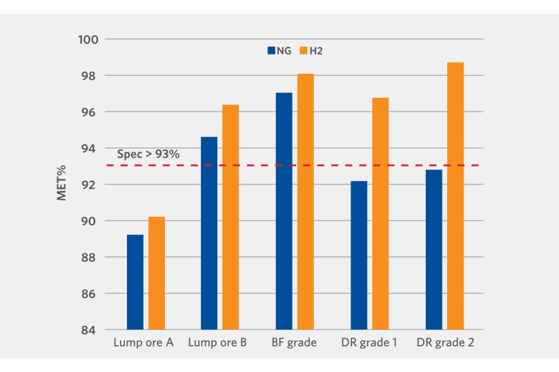
FIGURE 4.
100% hydrogen vs. reformed natural gas
Physical Strength Evaluation
The DRI generated by the Linder Test was also screened to determine the physical strength. The results demonstrate that apart from one lump oxide sample, the oxide reduced with hydrogen had relatively the same or lower fragmentation than those reduced with reformed natural gas (see Figure 5).
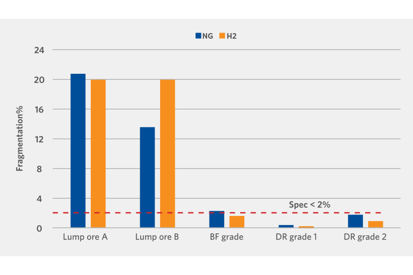
FIGURE 5.
Physical Strength Evaluation
Clustering Behavior Evaluation
Another evaluation performed was the cluster test. This test is performed at 850°C until 95% reduction is achieved.
Clustering or sticking occurs during the metallization of the oxide and is heavily dependent on the oxide type. It is critical to minimize the clustering behavior to avoid interruptions in the mass flow of the oxide in the shaft furnace and to maintain consistent metallization across the oxide bed.
Apart from one lump oxide sample, the clustering index of the hydrogen reduced DRI is lower than the reformed natural gas reduced DRI (see Figure 6).
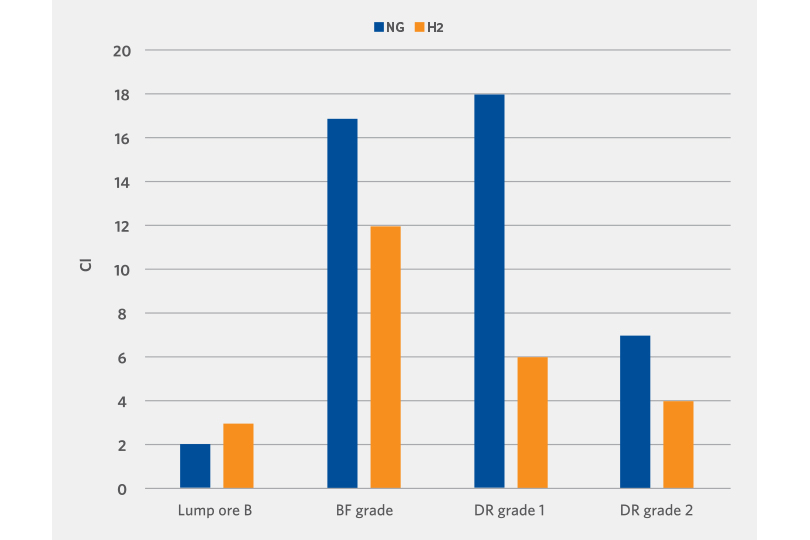
FIGURE 6.
Clustering Evaluation
CONCLUSION
The desire to decarbonize steel production is being driven by changing customer requirements and growing demand for carbon-friendly steel products coupled with a tightening of carbon emission regulations. A recent McKinsey study found that 14% of steel companies’ potential value is at risk if they are unable to decrease their environmental impact. The same study concluded that full decarbonization is possible with DRI using green hydrogen in the EAF.
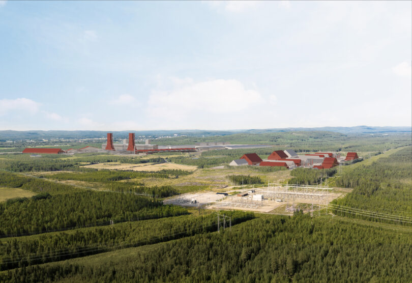
Midrex has the technologies to meet the challenge of achieving net-zero emissions in steelmaking. For those ready to go with 100% hydrogen operation, MIDREX H2 is available and being used in the first-of-its kind green steelmaking facility of H2 Green Steel in northern Sweden. And for those already operating a natural gas-based MIDREX Plant or wishing to transition in steps to complete hydrogen-based DRI, MIDREX Flex is the answer.
As we have for more than 50 years, Midrex is leading the way in innovative ironmaking solutions.
Related Reading
 Mar 25, 2026
 Feb 04, 2026