
DRI Production Using Coke Oven Gas (COG): Test Results of Thermal Reactor System™ (TRS®)
Natural gas continues to be the most ideal reducing gas source for the production of direct reduced iron (DRI). However, some areas of the world do not have access to low-cost natural gas in the volumes required for steady, sustained DRI production. For years companies have considered using coke oven gas (COG) to produce DRI. In theory the concept is simple; however, due to the composition of COG, a simple solution has not been readily available.
In June of 2012, Midrex Technologies, Inc. and Praxair, Inc. signed a strategic alliance agreement to develop and market the Thermal Reactor System™ (TRS®), which will allow the production of DRI with a variety of fuels including COG. TRS® will use an innovative partial oxidation technology developed by Praxair to convert hydrocarbon fuels into high quality, high temperature syngas suitable for DRI production in the MIDREX® Direct Reduction Furnace.
This article describes the Thermal Reactor System™ (TRS®) and presents the results of the final phase of development testing involving the operation of a TRS® Demonstration Plant at the Midrex Research & Development Technology Center in Pineville, NC, near Charlotte.
BACKGROUND
Coke oven gas (COG) is a byproduct of the coke-making process consisting of a complex mixture of typically 55 % H2, 7 % CO, 25 % CH4 and small amounts of CO2, H2O, heavy tars and volatile hydrocarbons. Today, most COG is used for heating applications, as a chemical plant feedstock or is flared, leaving its potential as a reducing gas untapped. Using COG for DRI production has always been of interest, but the challenges have been the conversion of methane to CO and H2 and cleanup of the tars and volatile hydrocarbons.
Midrex first started looking at methods of using COG for direct reduction in the 1970s. The principal problems involved the presence of unsaturated hydrocarbons, tars and liquids, as well as high levels of methane and sulfur compounds in the raw gas. The earliest studies focused on conditioning the COG to use it as a feed gas component for a MIDREX® Reformer. More recently, interest has turned to the possible use of COG in an MXCOL® Plant, which is designed specifically to use coal-derived gases as the reducing gas for the production of DRI products (see Figure 1).
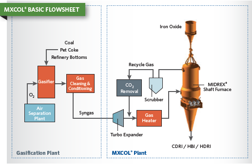
FIGURE 1.
MXCOL® Flowsheet
Recent developments in partial oxidation technology led Midrex to investigate the possibility of using it to condition COG as an appropriate reducing gas for an MXCOL® Plant. However, the need to add steam to the reactants to reduce soot formation resulting from the oxygen reactions has been a major concern. As a result, Midrex formed an alliance with Praxair, Inc., a leader in partial oxidation technology, to develop and market a new process technology for the production of DRI from a variety of fuels including COG.
PRAXAIR HOT OXYGEN TECHNOLOGY
In mid-2011, Praxair made a presentation to Midrex that covered a variety of technology developments which they were offering commercially. One of these was the Hot Oxygen Burner (HOB). Its unique features offered the potential to perform partial oxidation of hydrocarbons soot-free without steam injection. When this technology is combined with an extended thermal reaction chamber into which a stream of preheated COG is injected, the product gas leaving the reactor is suitable for use as a reductant source for direct reduction. All together, this equipment grouping including gas compression, preheating and reacting makes up what has become known as the Thermal Reactor System ™ or TRS®.
THERMAL REACTOR SYSTEM™ (TRS®)
TRS® employs Praxair’s HOB technology for partial oxidation of a variety of fuels including COG. The system produces an in-situ, hot, extreme velocity oxygen jet that rapidly entrains preheated COG, reforms the methane, breaks down heavy hydrocarbons and destroys the tars without the need for any catalyst. Reformed syngas then exits the TRS® and is fed into the MIDREX® Shaft Furnace to produce DRI.
In pilot scale tests with the HOB, over 96% tar destruction was achieved along with optimized methane reforming. In addition, operating conditions have been developed to avoid net soot generation.
Based on the results of the pilot scale tests, the decision was made in 2012 to construct a 1/10-scale demonstration plant at the Midrex Research & Development Technology Center in Pineville, NC, near Charlotte. In all, the demonstration plant operated for three campaigns covering more than 2000 hours during the 29-month project period. The plant operated on two major blends of COG feedstock, with toluene levels from 0-1.9 mol % and 100 % natural gas as feedstock. It also used four different gas combinations for the firing fuel of the HOB. The TRS® Demonstration Plant is shown in Figure 2.
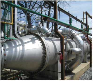
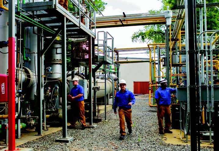
FIGURE 2.
TRS® Demonstration Plant
Midrex and Praxair completed the final phase of development testing in 3rd quarter 2014, and the Thermal Reactor System™ (TRS®) is now ready for commercial application. The TRS® will be jointly marketed by Midrex and Praxair.
TRS® DEMONSTRATION PLANT
The concept of the demonstration plant was to combine the primary gaseous components of coke oven gas, hydrogen, methane, nitrogen and carbon dioxide from liquid bulk sources and recirculate a portion of the syngas generated to supply the carbon monoxide required. A separate stream of toluene would be added at varying levels to study the BTX component of COG and its effect on system performance and syngas quality.
CAMPAIGN PLANNING
The test plan for 2013 called for campaigns to establish clear parameters for operation of the TRS®. Campaign 1 was expected to develop clear operating procedures for the demonstration facility, as well as develop a preliminary understanding of the range of the operating envelope of the facility. Campaign 2 was to establish the critical operating points for commercial operation of the TRS® units, as well as turndown and upper limits on system capacity. The nominal design capacities at different points in the demonstration plant are shown in Figure 3. The flowsheet for Campaigns 1 & 2 is shown in Figure 4.
Following completion of Campaign 2, a test plan for Campaign 3 was developed. It required the use of different fuels in the HOB. To accomplish this, the flowsheet of the demonstration plant needed to be modified for additional gas metering and compression (see Figure 5). These modifications and further commissioning corrections were completed by June 2014. The HOB also required some independent testing because its primary fuel had been only natural gas up to this point.
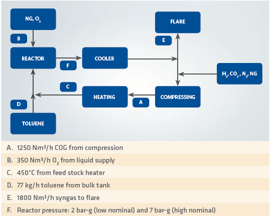
FIGURE 3.
Nominal design capacities at different points in the demonstration plant
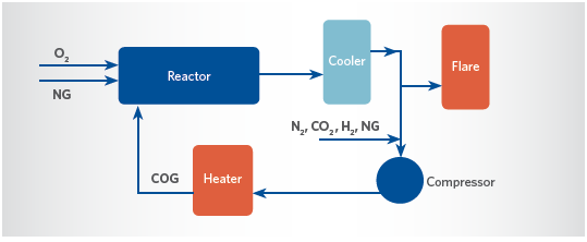
FIGURE 4.
TRS® Demonstration Plant Flowsheet for Campaigns 1 & 2
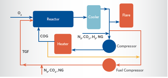
FIGURE 5.
TRS® Demonstration Plant Flowsheet Modified for Campaign 3
RESULTS OF TEST CAMPAIGNS
Campaign 1
The first campaign was run for 15 days in June 2013 and tested numerous COG feedstock combinations with varying toluene content and varying oxygen rates, expressed as a stoichiometric ratio, or SR. The objectives were to determine the range of operation for this system and to begin to define the soot generation relationship with regard to the reactor temperature and SR.
The system was run at 2.0 bar-g reactor pressure and was fed with the following COG feedstock composition range:
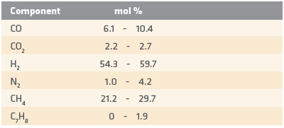
In Campaign 1, the SR was operated over a wide range, from 0.14 to 0.21. The best raw syngas quality was obtained near the center of the test range. This represented a major improvement over the prior tests in the lab-scale pilot facility, which ran best at an SR over 0.21. The improved SR is likely due to the reduced heat loss of the new reactor, 3.5 % versus 40-50 % for the prior lab-scale test reactor.
Other developments which were applied in the first campaign included a laser opacity measuring arrangement designed to quantify and trend the soot generated within the reactor and a sub-stoichiometric burner arrangement used to preheat and idle the system at temperatures in excess of the auto-ignition temperature.
After a follow up review, it was clear that one of the major objectives for Campaign 2 would be to reduce the plant operating variations and bring a better understanding of the soot generating conditions.
Campaign 2
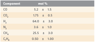
In Campaign 2, which ran for 20 days from late July into August, 2013 the operating plan was targeted for a much tighter control of feedstock and reactor conditions. A soot sampling arrangement was established to verify the laser readings and the laser opacity system also was modified to improve stability, in particular to overcome the system sensitivity to external temperature effects. The operating pressure of the reactor was increased to 3.3 bar-g to match the expected commercial design pressure then under consideration, and the COG feedstock target composition range was adjusted to:
During the second campaign, soot was filtered out of a slip stream of syngas from the reactor during 30-60 minutes sampling periods. The samples provided good spot validation of the laser opacity trends and the data required to determine the critical SR for minimum soot formation. The soot data collected is shown in Figure 6 and clearly shows the impact of toluene levels on soot generation.
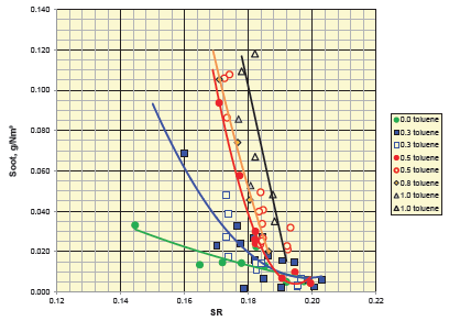
FIGURE 6.
TRS® Soot Generation at Various Toluene Levels
Two additional pieces of important data for DRI production from syngas are the temperature of the syngas and the residual methane contained in that syngas. Their interrelationship is shown in Figures 7 and 8.
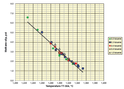
FIGURE 7.
Peak Reactor Temperature vs Methane Slip from TRS® in Campaign 2
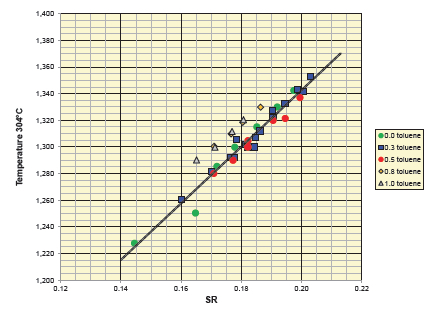
FIGURE 8.
Peak Reactor Temperature vs SR in Campaign 2
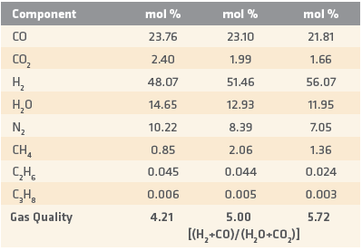
Based on the operating data from Campaign 2, the raw syngas produced from the TRS® reactor that was fed by the COG composition identified earlier would have a typical reductants-to-oxidants ratio [(H2+CO)/(H2O+CO2)] of about 6 for the uncooled raw syngas at 1340°C, as shown in the next column above.
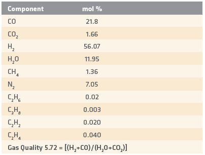
The reductants-to-oxidants ratio increases to about 15 when the raw syngas is quenched to about 40°C to reduce the H2O content. As a rule of thumb, for every 100 Nm³ of COG the TRS® produces 175-180 Nm³ of the raw syngas at approximately 1340°C.
Campaign 3
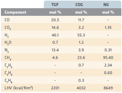
For Campaign 3, the remaining issue to be demonstrated was the use of the low heating value fuels in the HOB. Two different hot oxygen temperatures also were tested. The fuel compositions run during the test period ranged from top gas fuel (TGF), which was typical of spent reducing gas available in a DRI plant, to COG taken from the feedstock to the TRS®, as follows:
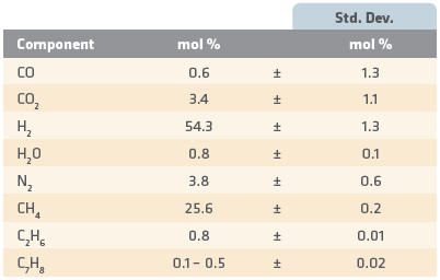
For Campaign 3, the TRS® feedstock analysis target reverted to the target from Campaign 1 and resulted in the following composition (next page):
The resulting syngas, produced from the above range of HOB gases and TRS® feedstock was as follows:
As with the previous campaigns, the major issues focused on the control of the peak gas temperature, the methane slip and the potential for soot generation in the reactor. These are each shown in Figures 9, 10 and 11. The use of lower heating value fuels was successful in generating a reducing quality gas with low CO2 content and free from significant soot generation. As would be expected, the lower the fuel heating value, the higher the oxidant level in the raw gas for the same peak operating temperature. The resulting gas qualities are easily improved with full or partial cooling of the hot syngas streams. The typical resulting H2O content would be between 9% – 10% for partial quench and 1.5% – 2.0% for a full quench.
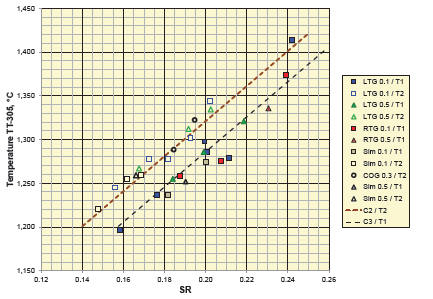
FIGURE 9.
Peak Reactor Temperature vs SR in Campaign 3 (T1 < T2 are hot oxygen temperatures)
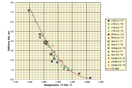
FIGURE 10.
Peak Reactor Temperature versus Methane Slip from TRS® in Campaign 3
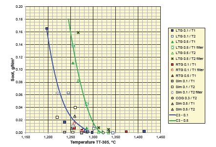
FIGURE 11.
Soot Generation versus Peak Reactor Temperature in Campaigns 2 and 3
TRS® FLOWSHEET INTEGRATION
There are two TRS® flowsheet options which can be used to add syngas and produce high quality DRI from COG. Both arrangements use the MXCOL® flowsheet as the principal arrangement of equipment for managing the removal of the oxidants (H2O and CO2) from the process stream. The two flowsheet options are the Feed Gas TRS® and the Bustle Gas TRS®, which are shown below in Figures 12 and 13.
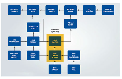
FIGURE 12.
Feed Gas TRS® Flowsheet
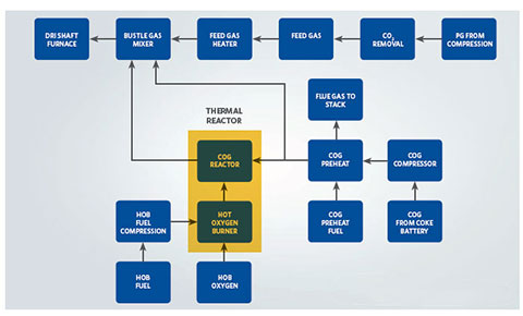
FIGURE 13.
Bustle Gas TRS® Flowsheet
The preferred option is the Bustle Gas TRS® flowsheet because it retains the residual heat from the TRS® reactions and utilizes it directly in the DRI production process. The heat helps convert the lower quality syngas and feed gas, typically about 8.5 quality (reductant/oxidant) ratio, to a 12.0 quality ratio at equilibrated conditions. Typical MIDREX® reformed gas has a quality ratio of 10.5 and after equilibration reaches a 12.0-12.5 quality ratio. Therefore, the production performance derived from TRS® syngas fits well into the normal performance curves for a MIDREX® Direct Reduction Plant.
Midrex also has developed a flowsheet that does not incorporate a recycle of spent process gases but rather exports the gases for use as burner fuels in other plant operations. This flowsheet requires approximately twice the COG per ton of DRI produced but yields about a 60-65% return of heating value in the export gas volumes. This option would fit best in larger integrated facilities where the DRI needs are less and the need for additional inprocess furnace fuels is significant.
CONCLUSION
Based on the results achieved during their multi-campaign developmental testing program, Midrex and Praxair are ready to take their Thermal Reactor System™ (TRS®) to market. TRS® can produce clean syngas from COG and other hydrocarbon sources for DRI production in a MIDREX® Direct Reduction Furnace. Analysis of COG input and sygas output is shown in TABLE I.
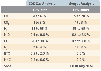
TABLE I.
Typical Results obtained from the COG Demo Test Operations
The commercial applications for iron and steelmaking are numerous. TRS® offers a solution for regions like India with limited access to natural gas for the production of DRI. TRS® technology can be retrofitted to existing plants or used for new projects, and it can provide up to 100 % of the reducing gas for a MIDREX® Plant.
TRS® also opens up new DRI production options for conventional integrated steel mills (coke oven/blast furnace/basic oxygen furnace), as seen in Figure 14. Using TRS® technology to process COG into a high quality syngas that can be used as reducing gas in a MIDREX® Reduction Furnace allows integrated steel producers to make optimum use of their coke resource. More iron can be produced for the same amount of coke, and that iron in the form of hot briquetted iron (HBI) can then be fed to a BF or BOF within the same integrated works. This would increase hot metal production while reducing specific coke consumption, thus greatly reducing the environmental impact of the steel produced. The HBI also could be used in place of purchased scrap in the BOF.
Benefits of TRS® when producing DRI are:
- Hot reduction zone reaction temperature (840°C)
- HDRI discharge temperatures (>700°C)
- Consistent DRI quality from close control of syngas quality and methane concentration to the furnace
- Improved product quality control flexibility, metallization and carbon
- Maximum utilization of the heavy hydrocarbons by breaking them down and then reforming to H2 and CO
- Increased plant operating efficiency and fewer maintenance issues due to reduced hydrocarbon cracking potential in the reducing gas heater
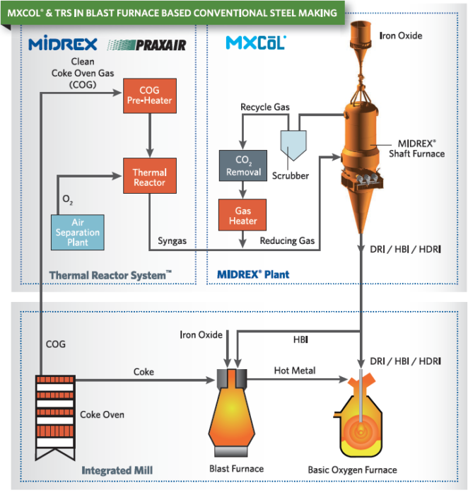
FIGURE 14.
TRS® with MXCOL® Flowsheet
(This article is adapted from the paper titled, “DRI Production using Coke Oven Gas (COG): Results of the MIDREX® Thermal Reactor SystemTM (TRS®) Testing and Future Commercial Application”, by G. Metius and H. Gaines, Midrex Technologies, Inc. USA; and M. Riley, L. Bool III and B. Damstedt, Praxair Inc. USA, and the article from 4Q2012 Direct From Midrex titled, “Increased Integrated and EAFs possibilities using Midrex/Praxair Thermal Reactor System™”, by Gary Metius)
Related Reading
 Jun 25, 2025
 Mar 21, 2024