
Meeting The Challenges of H2-Based Technology

Juan QuiñonezSenior Process Engineer
Articles by Juan
Jared HiltonChief, Proprietary Equipment Engineering
Articles by Jared
Ross GoldbergChief, Electrical & Instrumentation Engineering
Articles by Ross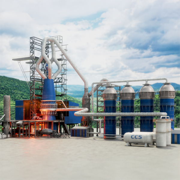
Design & Safety Solutions for New MIDREX® Plants
Introduction
As the steel industry challenges itself to significantly reduce carbon dioxide (CO2) emissions, steelmakers are placing a greater focus on reducing carbon emissions everywhere in their processes, including sourcing and utilizing larger volumes of lower-carbon raw materials such as direct reduced iron (DRI). The advent of new technologies, such as the MIDREX Flex® and MIDREX H2™, has made available very low-carbon DRI, allowing steelmakers to achieve increasingly challenging emissions targets. These new technologies are heavily focused on transitioning or replacing traditional natural gas (NG)-based direct reduction with hydrogen (H2)-based direct reduction, while maintaining the safety and reliability standards that have made Midrex the world leader in direct reduction technologies.
Using hydrogen in direct reduction facilities is not a novel concept; however, the transition to hydrogen-based operations introduces complex design and safety challenges. Midrex has taken the lead in adapting its technologies to support the steel industry’s initiatives to lower CO2 emissions and embrace green steelmaking by implementing new standards and engineering solutions in the plant designs for MIDREX Flex and MIDREX H2 technologies to ensure safe and reliable plant operation for which MIDREX® Plants are known.
This article explains how Midrex leverages its expertise in DRI plant design and optimization to mitigate these risks and hazards and provide DRI plants that can be safely operated with up to 100% H2 to help the global iron and steel industry achieve net zero-carbon goals.
Hydrogen Properties
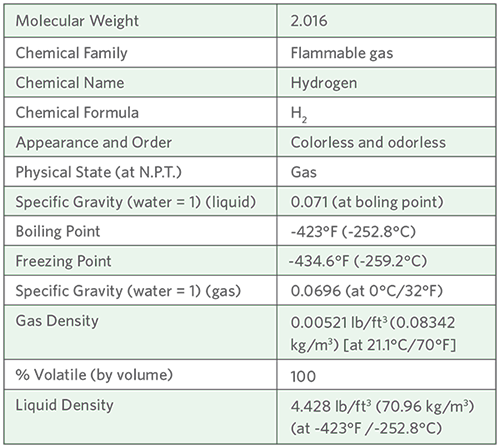
Hydrogen presents unique hazards including hydrogen embrittlement, hydrogen permeation, and the risk of hydrogen-related fires, explosions, and asphyxiation.
Hydrogen, the lightest gas, diffuses rapidly and poses unique challenges due to its high flammability and nearly invisible flame. Though non-corrosive in its pure state, its small molecular size increases the risk of leaks in gas-tight systems. Even minimal energy sources, such as static discharge, can ignite hydrogen, requiring rigorous containment and detection strategies. Additionally, a hydrogen atom’s small size can allow it to penetrate or permeate metals and create stress, cracks, and catastrophic failures if appropriate measures are not incorporated into the design.
The two most common impacts from the use of high percentages of H2 are embrittlement and permeation, especially in regard to instrumentation.
Hydrogen Embrittlement
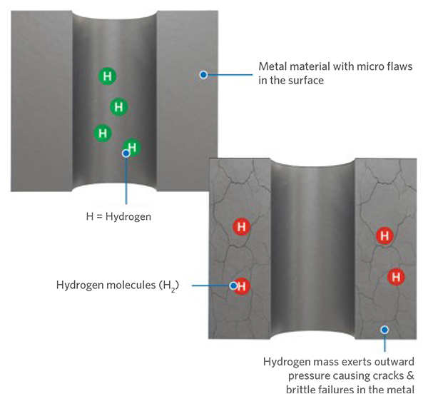
Pictured: Hydrogen embrittlement
Hydrogen embrittlement, also known as hydrogen-induced cracking or hydrogen attack, can significantly affect the integrity of metals in contact with H2, leading to structural instabilities and risk of failure. Materials such as high-strength steels and certain alloys are particularly vulnerable, especially at low temperatures (< 100°C).
Material selection is paramount in mitigating hydrogen-related degradation. Midrex ensures the materials for plant piping and equipment are chosen based on the process conditions and are specially designed to protect against the presence of hydrogen in the system. Instrumentation is also carefully selected to resist the negative effects of H2 in the process. Most notably, instruments used in hydrogen service need special considerations for wetted parts that come in contact with the process. These wetted parts typically are required to be manufactured from 316L stainless steel, plated Alloy-400, or Alloy C-276. Special O-rings may also be required for complete isolation of hydrogen from the non-wetted parts of the instruments.
Hydrogen Permeation
Hydrogen permeation occurs primarily in instrumentation that uses thin metal diaphragms, such as pressure transmitters or diaphragm seals. The small size of H2 atoms allows them to diffuse through the steel diaphragms and combine with other atoms to displace special sensing fluid in the instrument, causing measurement drift. If left unchecked, measurement instrumentation inaccuracies can lead to process inefficiencies or instabilities, or possible safety hazards. Hydrogen permeation effects are magnified by higher pressures, elevated temperatures, or even the presence of hydrogen sulfide (H2S) in the gas stream.
Hydrogen permeation through instrumentation membranes is typically prevented by proper material selection, such as gold-plated 316L stainless steel diaphragms. Although these instruments can be 40-60% more costly than non-plated options, the prevention of instrument measurement drift quickly justifies the additional expense in process streams with high H2 compositions. Additional engineering design mitigations, such as shifting diaphragms away from high temperature areas, also can reduce the risk of hydrogen permeation through critical instrumentation in the plant.
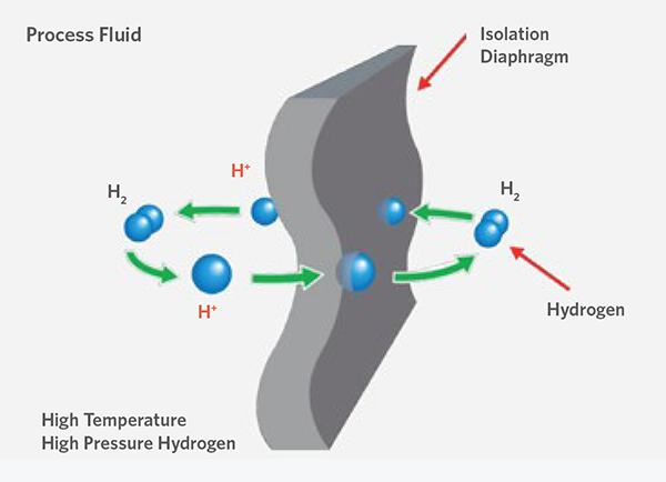
Pictured: Hydrogen permeation
Effects On Proprietary Equipment
Refractory Materials
The transition from conventional refractory materials used in NG-based operations to those suitable for high-H2 environments (exceeding 80%) presents significant challenges due to hydrogen-induced corrosion at elevated temperatures. Hydrogen aggressively attacks and degrades the oxide compounds commonly employed in refractory manufacturing, compromising structural integrity and longevity. In conventional MIDREX Plants (i.e., NG-based), the reformed reducing gas typically contains approximately 55% H2, exposing components such as the reducing gas duct, including the reheat duct, and the furnace linings to moderate levels of degradation. However, as H2 concentrations increase, the rate of refractory erosion and corrosion accelerates markedly.
A comprehensive series of tests were conducted under controlled conditions to evaluate the long-term performance of refractory materials exposed to high concentrations of hydrogen. Multiple physical properties were assessed before and after exposure, revealing that hydrogen induces weight loss in refractory bricks, with degradation severity directly linked to phosphate content. Phosphate-bonded bricks experienced substantial density reduction over a short exposure period, while non-phosphate bonded bricks retained nearly all the original density and physical integrity. High alumina-burned, phosphate-bonded bricks exhibited poor performance due to chemical instability under elevated hydrogen conditions. Hydrogen actively leached silica (SiO₂) and phosphate (P₂O₅) from the refractory matrix into the gas stream, resulting in increased porosity, reduced density, and diminished mechanical strength.
These findings highlight the critical vulnerability of phosphate-bonded refractories in hydrogen-rich environments and underscore the need to upgrade the hot face lining to compositions containing 75–85% alumina, which offer enhanced resistance to hydrogen-induced degradation and maintain structural reliability under aggressive operating conditions.
Reformer
In MIDREX Flex and MIDREX H2 plants, hydrogen is supplied “over the fence” by external providers and must be heated prior to entering the reduction furnace. In the MIDREX Flex configuration, hydrogen operations repurpose the conventional reformer as an H₂ heater, utilizing low NOx burners to minimize emissions. For existing installations, retrofit low NOx burner solutions are available through Midrex Global Solutions to support this transition.
In contrast, the MIDREX H2 plant employs specifically-designed electric heaters rather than a traditional NG reformer, aligning with decarbonization goals. Hydrogen introduces unique operational challenges due to its low molecular weight, which complicates sealing and containment, and its nearly invisible flame, which poses safety risks in the event of a leak. These factors necessitate specialized design considerations and safety protocols to ensure reliable and secure H2 integration across Midrex technologies.
Hydrogen operations require rigorous risk mitigation strategies and careful material selection to ensure safe and reliable performance under demanding conditions. Technically tight calculations for flange connections and hazardous gas sealing areas must be performed to ensure proper configurations of components. Installation of bolted and gasketed connections must be performed by trained and certified technicians following detailed procedures. Quality assurance is critical during both construction and ongoing maintenance, supported by engineered safeguards, operational controls, and designated exclusion zones. Compliance with standards such as ASME B31.12 for Hydrogen Piping and Pipelines ensures structural integrity and safety. Base materials are thoroughly evaluated for susceptibility to embrittlement, particularly in environments prone to High-Temperature Hydrogen Attack (HTHA), which occurs at pressures above 10 bar and temperatures exceeding 100°C.
To address these risks, new reformer tube designs have been developed with metallurgical and mechanical properties tailored to hydrogen service. These tubes are engineered to operate outside the Nelson Curve risk zones—exposed to high temperatures but not high pressures—thereby minimizing the likelihood of HTHA and extending operational life in hydrogen-rich environments.
Process Design Considerations
One of the most critical aspects to consider is how to handle a higher concentration of H2 in the process flowsheet. During plant operations, the plant is initially pressurized with nitrogen (N2) or seal gas, which has a molecular weight (MW) of around 28-30 g/mol. After establishing natural gas reforming, the reducing gases, H2 and carbon monoxide (CO), are generated, decreasing the MW in the process gas to ~17 g/mol; almost half of the original inert gas. Reducing gas derived from NG reforming contains a significant amount of CO, however, the hydrogen concentration is still higher in the mix (i.e., H2/CO ratio higher than 1.5), resulting in a net decrease of the molecular weight. During the H2 transition, CO is further replaced by hydrogen as reducing agent, generating a gas with a molecular weight of ~8 g/mol at higher hydrogen replacement stages.
This important change in composition of the gas presents two challenges to overcome during the compression stage: a decrease in the compression ratio from the compressor, resulting in a lower pressure rise, and the need for a higher process gas (PG) flow to sustain furnace conditions due to the endothermic nature of the H2 reaction. These two factors directly affect the design of the PG compressors. To meet the increased flow and pressure demands, a third compression stage becomes necessary. This additional stage is a centrifugal compressor, similar to the units typically used in the MIDREX NG flowsheet.
Figures 1A and 1B show the impact of the MW in the compression ratio for the same set of compressors, given that they could develop up to 6 barg max pressure when running with N2 and only up 4 barg when the MW drops to 19 g/mol. The green line mimics the system curve (pressure requirements by the PG loop) and it shows how the two align as the MW drops to the typical operating values.
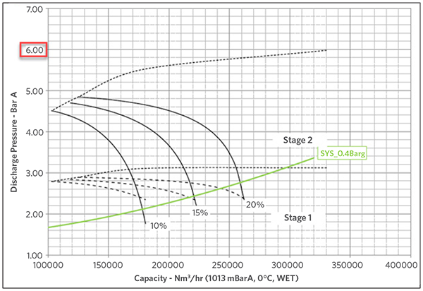
FIGURE 1A
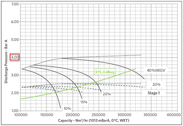
FIGURE 1B
Instruments and valves also get affected by the wider operational range for the molecular weight. Gases with different molecular weight generate different DP (Greek symbol delta, denotes small but significant change in pressure) readings through an orifice which need to be considered in order to have accurate control of the process. This is why it is so critical to consider changes, not only in MW (specific gravity), but also in pressure and temperature. All this is accomplished by applying temperature, pressure, and specific gravity compensation for flow indications which might suffer variations in those parameters. This is not a new concept in the Midrex design, but becomes critical when talking about hydrogen transition. Figure 2 shows a P&ID representation of the concept.
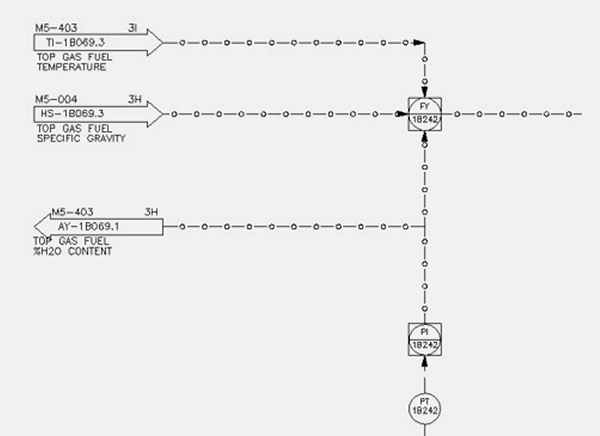
FIGURE 2.
Mass Flow Correction
The transition also impacts some of the main equipment in the flowsheet, particularly the reformer, which also serves as process gas heater. As hydrogen replacement increases, the overall energy requirement of the reformer decreases. This is because hydrogen is introduced from an external source and reduces the need for endothermic reduction reactions. Similarly, as the concentration of carbon-bearing components declines in the MIDREX H2 flowsheet, the energy requirements continue to drop, further lowering the thermal load on the external heater.
In contrast, the top gas scrubber experiences an increase in cooling load as hydrogen replacement progresses (see Figure 3). This is primarily due to the higher flow rate and moisture content in the top gas, both of which result from the reduction reactions. Consequently, the overall cold water demand increases with hydrogen introduction, prompting several additions to the flowsheet, such as cooling tower and associated pumps. The internal components of the top gas scrubber – including the throat, packing and mist eliminators – can be designed to accommodate the full range of operating conditions.
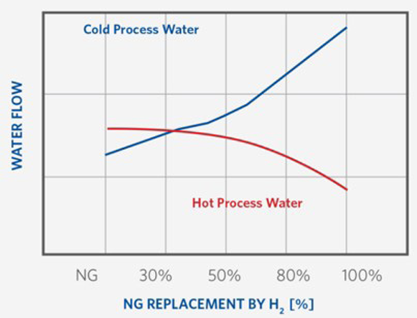
FIGURE 3.
Top Gas Scrubber Reaction to H2 Increase
In regard to the furnace, the higher gas flow per ton of product affects the sizing of both the furnace and the bustle ring nozzles. Proper sizing is essential to ensure proper gas distribution and to prevent potential fluidization issues during operation.
Hydrogen Safety Considerations
When designing industrial plants that utilize combustible gases in the process, it is important to properly define the hazardous area classifications for the facility to ensure equipment, instrumentation, and materials used in the design will not create additional risks of fires or explosions in the event of a gas release. Hydrogen is classified under NFPA (Class 1, Div 2, Group B) and ATEX (Zone 2, IIC or IIB+H2) as requiring a larger hazardous zone compared to natural gas due to its volatility and lower ignition energy requirements (see Figures 4 and 5). Midrex evaluates and incorporates these hazardous area designations into the plant engineering process, thus ensuring appropriate selection of equipment, instrumentation, and ventilation systems based on gas composition and release scenarios.
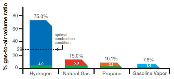
FIGURE 4.
Flame Range
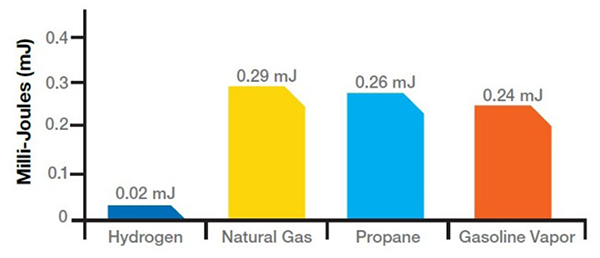
FIGURE 5.
Ignition Energy
Hydrogen has a wide flammability range (from 4-75% concentration in air) and a low energy requirement to initiate combustion. It burns with a pale blue flame with low radiant heat, which make it almost invisible in daylight and difficult to sense from a distance. Therefore, adherence to good practices of guarding and monitoring are necessary in enclosed locations of areas of potential leaks.
Hydrogen also can become an asphyxiation risk, as it displaces oxygen in the air. However, due to its light density, H2 tends to dissipate quickly and can accumulate in higher areas of buildings. Gas monitoring is one of the most important considerations in the plant, either by four-gas monitors and/or localized analyzers. Applying a proper confined space procedure is also extremely important before entering to any vessel during shutdowns.
Process Hazard Analysis (PHA) and Hazard and Operability (HAZOP) studies are integral to Midrex’s safety strategy for plant design. These evaluations, conducted by cross-disciplinary teams of engineering experts, assess operational deviations and ensure safe responses from the process in the event of risks to personnel, equipment, or environmental emissions. The methodology used is independent of gas composition, focusing instead on process knowledge and engineering design, and thus ensuring safe plant designs regardless of which MIDREX Plant design is being evaluated.
Hydrogen – Now & In The Future
The best option for reducing the steel industry’s CO2 footprint is transitioning ironmaking from the blast furnace to direct reduction and ultimately moving from natural gas to hydrogen as the energy source and reductant for producing DRI. Existing natural gas-based MIDREX Plants can incorporate up to 30% hydrogen replacement without needing any significant equipment or instrument modifications, thereby offering a pathway to reduced carbon emissions for well-established DRI facilities. MIDREX Flex technology provides immediate CO2 reduction for new plants and a stepwise approach for transitioning from natural gas to nearly 100% hydrogen with minimal equipment modifications and limited changes to operations.
Designing plants that operate on 100% hydrogen (MIDREX H2 technology) introduces complex challenges. However, through a combination of process modeling with proprietary furnace modeling and CFD software, innovation engineering-driven designs, and in-house laboratory testing Midrex can provide full-scale commercial plants that meet the high safety standards and operational reliability for which MIDREX Plants are known.
Related Reading
 Sep 29, 2025
 Jun 25, 2025