
Developing a Novel Electric Heater for the MIDREX H2 Process

Paul KazalskiResearch Engineer- Midrex Technologies, Inc.
Articles by Paul
Dr. Pei Yoong KohManager, Technology Research- Midrex Technologies, Inc.
Articles by Dr.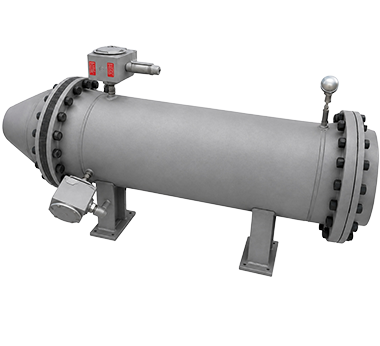
Introduction
Ongoing efforts to decarbonize the steel industry have focused on replacing fossil-fuel-based processes with carbon-free alternatives. One of the most promising pathways is to replace natural gas with green hydrogen and renewable electricity to power conventional direct reduction (DR) plants.
To that end, Midrex Technologies, Inc. has developed MIDREX H2™, an evolution of the MIDREX® Process capable of producing direct-reduced iron (DRI) at full industrial scale (1.6–2.5 million tpy), while avoiding carbon dioxide emissions. MIDREX H2 replaces the standard reformer with specialized electric heaters that supply energy to recycled process gas supplemented with over-the-fence green hydrogen (Figure 1). This eliminates natural gas consumption in two ways: hydrogen serves as the primary reductant in place of co-reformed natural gas, and electric heaters replace the reformer’s burners, which previously supplied the thermal energy for co-reforming and raising the bustle gas temperature.
The design and construction of these electric heaters is the culmination of a cross-disciplinary development effort. Although electric heaters are established technology in industrial applications ranging from petrochemicals to power generation1, their use as a substitute for methane co-reformers
in a MIDREX® Plant is novel. Midrex partnered with Tutco Sureheat to develop the design and then validate it through the following rigorous test program:
- Continuous operation of a single-element prototype with high gas outlet temperature and carbonaceous compositions.
- Multiple power interruptions of the single-element design to simulate plant upset conditions.
- Development of a pilot-scale prototype providing heating to a gas mixture that matches the expected conditions of a MIDREX H2 plant.
During testing and subsequent ex-situ analyses (SEM-EDX, XRD, and visual inspection), particular attention was paid to the physical properties of the heater wire, which was shown to retain its tensile strength, electrical resistivity, and resistance to metal dusting even after prolonged exposure to MIDREX H2 conditions. These analyses thus validated the electric heater design as a viable replacement for the conventional reformer, confirming the feasibility of the MIDREX H2 flowsheet.
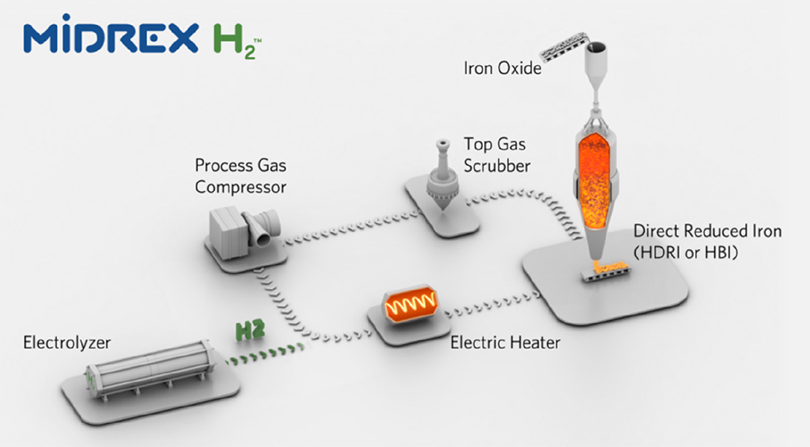
FIGURE 1.
Diagram of the MIDREX H2 flowsheet.
Objectives
The primary purpose of the testing program was to prove the readiness of the novel electric heater technology inside a MIDREX H2 plant. This included five key objectives:
- Demonstrate the electric heaters can supply sufficient energy: for every ton of DRI, the heaters must supply 507 Mcal to the reducing gas.
- Optimize heater geometry for efficiency, cost-effectiveness, and longevity.
- Prove the robustness of the electrical circuit in a demanding environment.
- Monitor the heating element’s electrome-chanical properties over time.
- Observe any chemical degradation of the element wire caused by chemicals such as hydrogen sulfide and carbon monoxide.
Table 1 summarizes the three operating cases that the electric heaters must service. The Carbon Case uses a small amount of natural gas to introduce carbon into the DRI product; the Hydrogen Case uses 100% green hydrogen; and the Nitrogen Case is used for hot commissioning and plant idling.
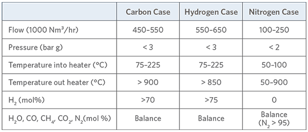
TABLE I.
Summary of the operating cases anticipated in a MIDREX H2 unit.
Single-Wire Longevity Testing
The first step toward a commercial heater was to test a single wire element under typical MIDREX H2 operating conditions. The wire was required to heat a mixture of carbon monoxide, carbon dioxide, hydrogen, water vapor, methane, and nitrogen continuously to 1,000°C for 500 hours. The program evaluated the robustness of the electrical circuit, the element’s ability to endure carbon deposition, the absence of strength creep, and the consistency of operation over the full test duration.
Carbon deposition was a particular area of focus. Solid carbon can form in the presence of a catalyst if the following reactions are thermodynamically favorable:
- The Boudouard reaction (2CO ↔ C + CO₂).
- The reverse water-gas shift reaction (H₂ + CO₂ ↔ CO + H₂O).
- Methane decomposition (CH₄ ↔ C + 2H₂).
Carbon formation is not necessarily a problem, but an electric heater can be compromised if solid carbon accumulation restricts process gas flow within the element, or if carbon chemically reacts with the wire material—a phenomenon known as metal dusting.
The Electric Heater Test Facility (ETF), constructed at The Midrex Technologies Research and Technology Development Center, comprised a recirculating loop that continuously preheated, heated, and cooled the process stream to minimize make-up gas consumption. Fresh, preheated dry feed gas was introduced via a manifold connected to cylinders of pure gases, each with its own mass flow controller. Vaporized water was introduced through a liquid flowmeter and humidifier, and hydrogen sulfide was supplied from a 500 ppm H₂S cylinder balanced with nitrogen. Downstream of the electric heater, a water-cooled heat exchanger returned the gas to initial conditions, with a portion vented to a flare and the remainder recycled (Figure 2).
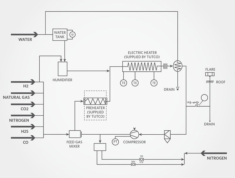
FIGURE 2.
Block diagram of the Electric Heater Test Facility (ETF).
The heater element was equipped with upstream and downstream pressure taps to record differential pressure in real time, temperature probes at both ends to calculate the change in gas enthalpy, and three optical temperature monitors designed by Tutco Sureheat to track wire temperature across its length. Electrical power was controlled by Tutco’s control panel, which included a silicon-controlled rectifier (SCR) and overload protection with shutoff interlocks.
Throughout the 500-hour test, the wire temperature, wire resistance, and gas outlet temperature remained stable, indicating that the heater element delivered reliable energy to the gas stream. Post-test tensile strength analysis showed comparable strength to a virgin wire. SEM-EDS analysis revealed that, although some carbon formed at certain sections of the wire, there was no evidence of metal dusting at any point along the element. SEM microscopy could not detect voids in the grain structure even at 20,000× magnification. All evidence confirmed that the wire withstood the expected MIDREX H2 operating conditions without failure.
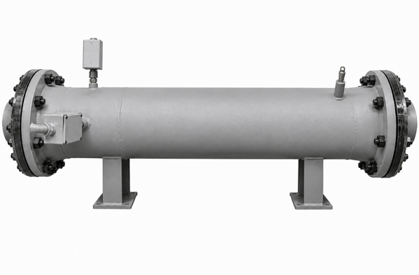
Pictured:
Model of single-element bench-scale electric heater used in the ETF.
Single-Wire Cycling Test
The next test program evaluated whether the heater element could withstand upset conditions (plant trips) without damage. A typical DRI plant may only experience a few trips per year, so surviving fifty full-to-zero-load cycles would represent a lifetime’s worth of shutdowns.
The ETF was repurposed for this test. Rather than maintaining continuous full-load operation, the energy supply was abruptly disconnected while process gas continued to flow, causing the wire temperature to drop by hundreds of degrees per minute. Each cycle ramped the gas temperature at 10°C per minute to a peak of 1,000°C, stabilized for two minutes, then rapidly cooled to 200°C, potentially weakening the element via thermal shock. The full cycle took about one hour and twenty minutes (Figure 3).
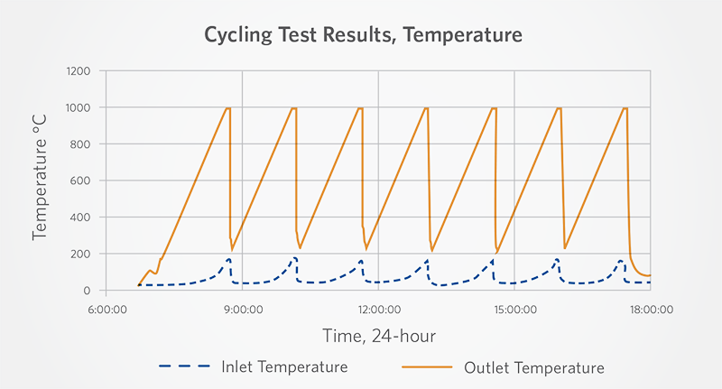
FIGURE 3.
Trends of inlet and outlet gas temperature over some period of time.
Wire performance appeared unchanged after fifty cycles. The regularity of power, current, and voltage across cycles confirmed that the wire’s resistive properties remained intact. SEM-EDS imaging showed no evidence of metal dusting or other chemical attack, and tensile strength testing yielded results comparable to those of a virgin wire. All evidence showed that the heater element can withstand repeated trips without deterioration (Figure 4).
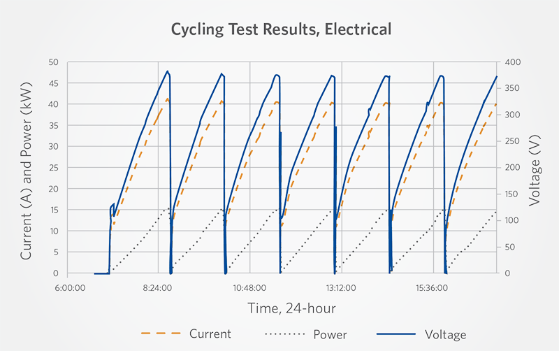
FIGURE 4.
Trends of electrical data (current, voltage, power) collected over 12-hour period during cycling test.
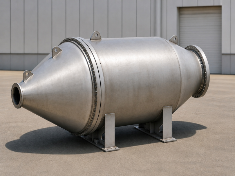
Pictured:
Model image of a multi-element prototype of the electric heater used at the MPF.
Prototype Longevity Test
Having demonstrated that a single element could survive both extended continuous operation and repeated thermal cycling, the next phase was to construct and test a multi-element prototype under full-load plant conditions. The prototype comprised twelve heater elements in parallel and was too large for the ETF, requiring a purpose-built Heater Pilot Facility (HPF) operating on the same recirculating principle but at a larger scale (Figure 5).
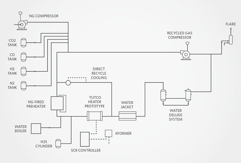
FIGURE 5.
Block diagram of the Heater Pilot Facility (HPF).
The scope was twofold:
- Simulate the inlet gas conditions (composition, flow rates, pressure, and temperature) of reducing gas in a MIDREX H2 unit,
- Safely provide continuous cooling for reducing gas exiting the electric heater (>1000°C).
The scale-up also required a more sophisticated power supply. The 12-element prototype’s SCR, supplied by Tutco Sureheat, controlled energy delivery and individually distributed power across three power leads. A step-up transformer converted the facility’s standard 480 VAC supply to the higher voltages expected in commercial design, while independent power monitors and an electrical disconnect ensured safe and reliable operation.
It was important that Midrex obtained accurate wire temperature data during operation of the Electric Heater Prototype, particularly when the heater was operating at full capacity. In order to do this, the piping of the HPF was designed such that a camera could have a clear view of the outlet of the heater elements (Figure 6). Ametek LAND’s infrared thermal imaging camera detects the radiation emitted by hot solid objects (< 500 °C) and can convert that detected radiation into temperature if the emissivity of the material is known. The data from the thermal camera was recorded in real time and stored onto the HPF’s data server. Using this information, it was possible to adjust process conditions in the HPF and observe its effect on wire temperature. It was also possible to measure the temperature of individual wire elements in order to minimize temperature maldistribution. Using the thermal camera’s data, it was possible for Midrex to optimize its design to ensure that the wires don’t overheat and that the temperature profile is even, which will prolong the life of the heater.
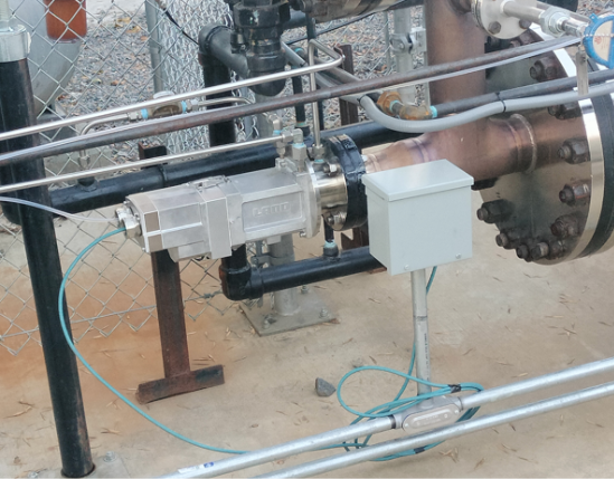
FIGURE 6.
Ametek LAND's infrared thermal imaging camera installed at the HPF.
Testing at the HPF included dedicated runs for the Nitrogen Case, the Hydrogen Case, and the Carbon Case. The focal point was a two-week longevity test under the Carbon Case. Temperature probes upstream and downstream of the heater measured the change in gas enthalpy. A differential pressure tap provided real-time pressure change data, which could indicate carbon accumulation across the twelve elements. The SCR controller recorded and adjusted power, voltage, and current in real time to deliver steady outlet gas temperatures (Figure 7).
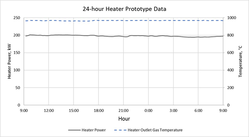
FIGURE 7.
Electrical power and outlet gas temperature of the prototype over a 24-hour period.
Post-test examinations included a full physical inspection of all twelve elements, module supports, fittings, and the prototype body itself, with before-and-after measurements to check for displacement that might indicate eventual failure. Electrical resistance was measured before and after testing. Sections of wire were sent to Kobe Steel Limited’s laboratories in Japan for SEM-EDS microscopy, grain size analysis, and line analysis.
The results confirmed that multiple heater elements in parallel can operate at full load across all three operating cases without signs of deterioration. Physical measurements and electrical resistance remained consistent, and microscopy revealed no metal dusting or significant phase transformation. These results prove that the heater design functions as intended as a module.
Conclusion
The MIDREX H2 process depends on the continuous, reliable operation of these novel electric heaters. Midrex Technologies’ multi-year test campaign has systematically addressed the foreseeable risks. Each successive program—from single-wire longevity to thermal cycling to multi-element prototype testing—built on lessons from the previous stage and increased in complexity, allowing steady maturation of the technology. With the successful completion of the Prototype Longevity Test, Midrex Technologies has de-risked the electric heater as a carbon-free replacement for the conventional reformer and demonstrated the feasibility of the MIDREX H2 flowsheet.
Acknowledgments
Midrex would like to acknowledge the efforts of Tutco Sureheat for designing and constructing the bench-scale and pilot-scale electric heaters and their control panels. We also thank the University of New Hampshire and Kobe Steel Limited’s Materials Research Laboratory for performing microscopy and strength testing of the heater wires after each test program.
References:
- Fischer, K. “Design Considerations for Electric Process Heaters”, July 2025.
Accessed at: https://www.eastman.com/content/dam/eastman/corporate/en/literature/s/sfehtf19990.pdf - Perry, R. H. & Green, D. W. (Eds.), Perry’s Chemical Engineers’ Handbook (7th ed.) (1999; McGraw-Hill). Table 2-194, pp. 2-162 and 2-163.