
Maximizing Iron Unit Yield from Ore to Liquid Steel (Part 2 – DRI physical properties and DRI handling and storage)
Christopher Manning, PhDMaterials Processing Solutions, Inc.
Articles by Christopher
Vincent F. Chevrier, PhDGeneral Manager – Business Development
Articles by Vincent
This is Part 2 of a three-part series on getting the most from raw materials, which is focused on the four interrelated factors that influence iron unit yield via the DR/EAF route:
- Ore selection (Part 1)
- DRI Physical properties (Part 2)
- DRI handling and storage (Part 2)
- Melting practice (Part 3)
INTRODUCTION
DRI products provide value to steelmaking operations as highly metalized, low residual iron units. Product quality – and hence value to the steelmaker – can be directly impacted by what happens to the DRI prior to it being melted. The extent of its value depends on maximizing the amount of iron units reaching the melting furnace by minimizing fines and maintaining product metallization after production.
DRI products, like other forms of iron, have the potential to degrade over time especially if not properly handled and stored. Steelmakers largely have control over maintaining this quality, if they take the right measures. Part 2 of the series, “Maximizing Iron Unit Yield from Ore to Liquid Steel”, examines the effect of the physical properties of DRI on resistance to fines generation and metallization loss and the measures that can be taken to maintain the value of DRI during handling and storage.
PART 2 – DRI PHYSICAL PROPERTIES
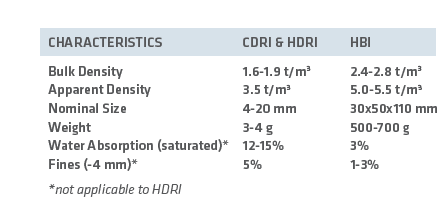
TABLE I. Typical Physical Characteristics of DRI Products
All forms of DRI have similar chemical characteristics because they are derived directly from iron oxide pellets and lump iron ores. The main difference is their physical characteristics (TABLE I), which lead to differences in behavior in handling and storage, as well as when contacted by water.
The first plants produced only a DRI product that was cooled to close to ambient temperature prior to discharge (CDRI). As demand for DRI increased in areas where the production of DRI was not feasible, a product with excellent handling and shipping characteristics was needed, which resulted in the introduction of hot briquetted iron (HBI). Over time EAF steelmakers with captive DRI plants (those adjacent to or nearby a melt shop) wanted a way to take advantage of the heat contained in DRI immediately following reduction without cooling, which resulted in the introduction of hot DRI (HDRI) and the means to transfer it to the melting furnace at near its discharge temperature.
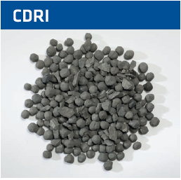
COLD DRI (CDRI)
Most direct reduction plants built to date produce CDRI. After reduction, the DRI is cooled in the lower part of the reduction furnace to about 50° C. Typically, CDRI is used in a nearby EAF shop as part of the primary metallic charge either in the scrap bucket or by continuous feeding.
CDRI has a sponge-like structure (hence the term “sponge iron”) comprising a network of interconnected pores, many of microscopic size, creating a large internal surface area. Measurements show surface areas of 1 m2/g, which is about 10,000 times greater than solid iron spheres of the same size. This large surface area facilitates the reduction of iron ore to DRI; however, it is prone to generate significant fines during handling and storage and encourages reactivity with oxygen when exposed to air and water. Therefore, CDRI must be kept dry to prevent oxidation (rusting) and loss of metallization.
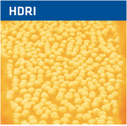
HOT DRI (HDRI)
This form of DRI allows the steelmaker to take advantage of the sensible heat (thermal energy whose transfer to or from a substance results in a change of temperature) to increase productivity and/or reduce production costs. HDRI, which already is above the ignition temperature (>200° C/390° F), will burn if contacted by air; therefore, care must be taken when handling and transporting it from the DRI plant to the steel mill. HDRI can be transported from a MIDREX® Shaft Furnace to a nearby steel mill at up to 650° C by one of three methods: enclosed and insulated conveyor, specially configured transport vessel or HOTLINK®, a system for direct feeding of HDRI to an EAF. Some HYL plant are equipped with a pneumatic transport system for handling hot DRI.
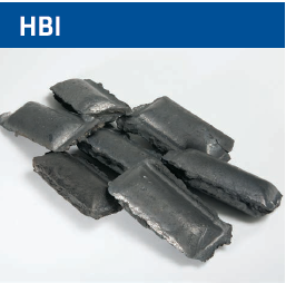
HOT BRIQUETTED IRON (HBI)
HBI is produced by compacting pellet and lump DRI under extremely high pressure at temperatures in excess of 650°C, as it exits the reduction furnace. The compaction closes the major voids, increases the density, and reduces the internal surface area of the DRI. As a result, HBI absorbs 75% less water than CDRI and produces less fines, which make it the preferred merchant DRI product. Its enhanced physical characteristics enable HBI to be stored and transported without special precautions under the International Maritime Organization (IMO) solid bulk cargo code. The size and density of HBI make it a desirable feed material for the EAF, blast furnace (BF), and basic oxygen furnace (BOF). Each DRI product, no matter how it is made, requires special considerations to maintain its value. Therefore, the yield and the degree of metallization (the percentage of metallic iron by weight exclusive of the iron bound up with oxygen as iron oxide, FeO) are key factors in determining DRI value. In addition, there are safety concerns that if not addressed could negatively impact a user’s bottom line. These are factors that apply to all three DRI products during handling and storage; however, the ways to address these issues vary to a degree for each particular DRI product.
DRI HANDLING
Material handling equipment selection and system design have a huge impact on how much fines will be generated during handling. The cost of fines generation should be considered when evaluating equipment options. The annual cost of operating a poorly designed system with high handling losses warrants the investment of capital to reduce yield loss, and payback/ROI can be very fast. As an example, consider a DRI handling system moving 1.6 million tons of product per year. Every 1% of material loss to spills or breakage will result in a loss of $5,600,000 per year at $350/ DRI ton. Fines generation on the ore handling side of a typical DR plant can be anywhere from 2% to over 5%. Fines generation and spillage on the DRI handling side can be 3% to 7%. These losses add up to large costs and represent a significant opportunity to invest in technologies that prevent loss or recover this material.
To preserve product quality, care must be taken to varying degrees with each product. As a general rule, users should try to minimize any unnecessary handling of the product. A material handling system should be designed for the minimum number of transfer points required to move material from point A to point B and with the shortest drops. The easiest way to minimize the number of transfer points is to take material along the straightest path possible. However, care should be taken not to compromise metering and feed control in an attempt to eliminate all transfer points. Spillage from overloaded belts may lose more material than breakage through the extra transfer point of a feeder.
A typical DRI handling system for a captive DRI plant may include the operations listed below.
CDRI and HBI
- Conveying/transporting CDRI to storage silos
- Discharging/reclaiming CDRI from storage silos
- Conveying/transporting CDRI or HBI to short-term storage at EAF melt shop
- Reclaiming CDRI or HBI from short-term storage
- Conveying/transporting CDRI or HBI to EAF
- Charging CDRI or HBI to EAF
HDRI
- Discharging HDRI from reduction furnace to pneumatic transport system, insulated hot transport conveyor or insulated hot transport vessels
- Transporting/conveying HDRI from reduction furnace
to EAF melt shop - Charging HDRI to EAF from pneumatic system, insulated conveyor or transport vessels
- Direct gravity feeding HDRI from reduction furnace to EAF melt shop (if equipped)
Yield losses during handling and storage arise from the following areas:
- Material spillage from conveyor belts and mobile equipment handling
- Material breakage and degradation at transfer points and through mobile equipment handling
- Material storage and reclaim
- Dust collection losses, including fires
- Degradation during storage
Breakage and Spills
During the handling of DRI products, breakage and spillage can account for significant losses of product. Handling losses can exceed the impact of total iron content or gangue content on the total yield from iron ore to liquid steel. However, handling losses often are absorbed by different operating areas and are not accounted for in total.
CDRI pellets are susceptible to breaking into chips and producing iron-laden dust during handling and between various types of storage (covered outdoor piles, silos, and warehouses). A frequently quoted estimate for CDRI breakage due to handling is 0.25% loss per 2-meter drop. This number can be much larger for weaker material, longer drops or poorly designed transitions. Fines and chips generated during handling will oxidize much faster than whole DRI products. A conservative number is 15% loss for 6.35 mm fraction material after exposed (outdoor) storage for a month.
The definition of what constitutes chips, fines, and dust is often a subject of debate. Many end users will call coarse fines (~3mm) dust or non-prime material. Depending on the user’s material handling system and the exhaust system on the melting furnace, there may be very little or zero recovery of this material. Material that leaves the DR plant as “chips and fines” is likely to continue to break down to dust through subsequent handling, stacking, and reclaiming steps. Effective screening of chips and fines at a size that complements the end steelmaking operation is a critical element of producing “high quality” DRI products. Once this undersized material is separated through screening, an economic recovery method must be identified and implemented.
Although HBI is a much more durable material than CDRI, HBI is also subject to breakage when quality is poor and/or if the material is handled very roughly. Customers paying for merchant HBI expect mostly whole briquettes and limited amounts of chips and broken briquettes. HBI should be more stable, more easily handled than DRI, and much less dusty than DRI. Up to a limit, HBI also presents an opportunity to recycle metallic chips, fines, and dust back into the hot briquetting machines. Small amounts of metallic fines are beneficial, but larger amounts can complicate the briquetting operation and can reduce the strength of the resulting HBI if the fines recycling is poorly managed.
HDRI can be transferred from the DRI plant to the melt shop by hot transport vessels, hot transport conveyors or pneumatic transport, depending on the distance between the DRI plant and the melt shop or by direct gravity feeding in the case of a close-coupled reduction furnace (MIDREX HOTLINK®) and EAF. Hot transport vessel systems employ ladle-type insulated vessels that are transported on flat-bed trucks and can be maintained at temperature if the melt shop is delayed in accepting the HDRI. Pneumatic transport systems use gas to blow DRI at high velocity through pipes to the EAF or a product cooler. The high velocity and resultant turbulence can cause significant breakage and erosion of the HDRI, especially at bends in the pneumatic line. This method can result in fines generation of as much as 8-10%. Hot conveyor systems using enclosed conveyor buckets are less jarring and greatly reduce HDRI fines generation.
Most of the breakage will occur at transfer points and stacking and reclaiming steps. A frequently quoted estimate for DRI handling breakage is 0.25% loss for each 2 meter drop the material experiences. This number can be much larger for weaker material, longer drops or poorly designed transitions. In fact, it is possible to have as much as 2.5% breakage through a single transfer point if no attention is paid to these issues. The amount of breakage also can be much lower for well-designed transitions, almost regardless of drop height.
For an existing oxide pellet or DRI material handling system, it is important to:
- quantify the material breakage at each stage or transition in the system,
- perform a screen analysis of samples throughout the material handling system, and
- use this data to prioritize problem transitions and correct them.
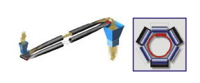
FIGURE 1. Pipe belt conveyor [1], [2]
Because pipe belt conveyors make horizontal turns, they can eliminate transfer points. In addition, pipe belts have much less spillage as compared with conventional belts. Dribble from carry back material on the return side is contained to just the head and tail. Because the material being carried is wrapped up in the conveyor belt, even in a belt over-fill condition material spillage is limited to head and tail.
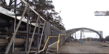
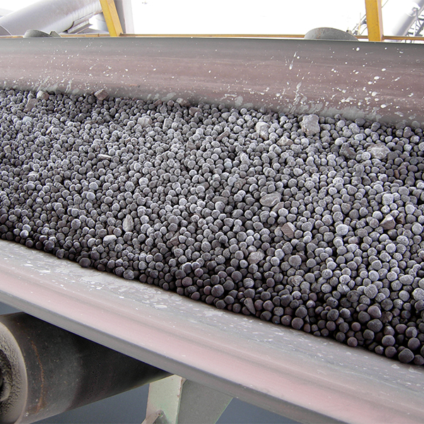
FIGURE 2. Pipe Belt Conveyor Carrying CDRI [3]
TRANSFER CHUTES
Transfer chutes are a necessary component of a material handling system because material must be loaded onto and discharged from conveyors at some point. Transfer chutes often are poorly engineered with harsh direction changes and high energy impacts. This is not a major issue for many bulk materials, and functional transitions that connect one conveyor to the next are perfectly acceptable. However, rough transfer points lead to DRI breakage, rapid chute wear, and excessive dust generation.
Conventional wisdom about transfer chutes has dictated “low and slow,” meaning slow moving conveyors with minimum drop heights at conveyor-to-conveyor transfers. Unfortunately, this can cause some problems, as very low transfer heights leave little room for belt cleaning (scraper or brush) systems. Low transfer points also leave little room to collect the material leaving the conveyor head pulley and redirect it in the direction of travel of the receiving belt. The result is a transfer point where material “flops” onto the receiving belt in a very disorganized fashion. This can put a large amount of lateral pressure on the loading zone skirting system. Even when aiming for the lowest possible drop height through a transition, there is a minimum which is set by the size of the head pulley, the height of the receiving conveyor skirt board system, and other considerations.
Material will accelerate to 1000 ft/min vertical velocity through a drop of only 4.5 feet. With only 4.5 feet of height to work with, there is no chance of collecting the material in a chute and organizing its speed and direction. In most instances, it is better to use a slightly longer drop that leaves room for a belt cleaning system and a well-engineered transfer chute to the receiving belt.
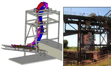
FIGURE 3. Inertial flow chute handling pelletized iron ore [4]
A major contributor to dusting at transfer points is “induced air flow.” When material particles are in free-fall, the particles separate from one another, drawing air into the space between the particles. When the material experiences a collision inside a receiving silo, onto a receiving conveyor or onto a stock pile, the space between the particles collapses and ejects the air that was entrained during free-fall. This can generate more than 10 times the air volume of the displaced volume of the material itself. This is frequently a major source of error in sizing dust collection equipment. Controlling the velocity and shape of the material stream through a well-engineered transfer chute can dramatically reduce the amount of induced air flow generated by the transfer point.
MATERIAL STORAGE AND RECLAIM
DRI products are somewhat like fresh fruit. Although they don’t have an expiration date they are best consumed when “fresh.” As with fruit, this may not always be possible, so the products may need to be placed in storage to preserve their quality and value.
HDRI is not intended for long-term storage but can retain much of its heat when needed to wait for a charging cycle or to be transported to a different nearby melting vessel. This is a temporary option when using hot transport vessels and not really an option when using pneumatic or conveyor bucket systems.
Outdoor Storage
HBI is normally stored outdoors in exposed piles built on a firm, well drained surface. Bulk piles of HBI tend to dissipate heat rapidly due to its good thermal conductivity characteristics and its shape and form that create voids in the pile. HBI, like scrap, can rust. Rusting has been observed to reduce its metallization by less than one percent per month even in salt-laden, humid air and frequent, heavy rainfall conditions.
CDRI can be stored safely in open, well drained piles if it will not be moved until it is used in the melt shop. Rain can only penetrate the stack to a certain depth, typically less than a meter. Although the resulting corrosion will reduce the metallization, as described earlier in this article, the stack should not overheat unless additional material covers the wet area. This will insulate the wet iron and prevent the dissipation of the associated heat, which can cause the pile to overheat and can lead to ignition.
The following precautions should be followed when storing DRI products outdoors:
- Build pile on a firm base, such as concrete, and insure proper drainage to prevent the intrusion of water under the pile. The base should provide protection from moisture in the ground. A sealant layout of tar, bitumen or some other material impervious to water should be laid down before the concrete is poured.
- Avoid excessive fines content in the pile.
- In the case of cold DRI (CDRI), cover the pile to keep DRI dry and to prevent air stacking in the pile.
- Separate any DRI that has been wetted or has a temperature in excess of 65° C and follow the same precaution as for bins and silos.
A DRI pile will warm up to about 60°C/140° C as steaming occurs but will cool down again to ambient temperature when the water is evaporated. Normally it is not necessary to take additional action if the pile is steaming as long as the temperature does not exceed 100°C/212° F.
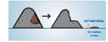
FIGURE 4. Method for controlling hot material in a storage pile
In case of a pile of DRI overheating to temperatures in excess of 100°C/212° F, the material should be removed from the pile and spread out on dry ground in a layer of about 0.5 meters using a track-equipped bulldozer or front-end loader, as shown in Figure 4. Another method is to bury the pile under sand or other suitable material to cut off the oxygen supply.
Important note: water should not be sprayed on an over-heated DRI pile under normal conditions. However, as a last resort in case of a runaway fire, the pile should be inundated with a strong water stream. Firefighters should be prepared for violent steaming and hydrogen flashing resulting from such action.
Storage Bins and Silos
Storage bins and silos are used to protect DRI products when there is a time delay between arrival and when they can be used or shipped. Badly designed silos can create operational problems and a decrease of product quality. The design of silos should be determined always on the basis of the material flow properties of the bulk solid(s) to be stored. The expenses for testing and silo design are small compared to the costs of lost production, quality problems, and retrofits that may be needed because of irregular flow patterns.
The following precautions are recommended when storing DRI products in bins and silos:
- Any DRI at a temperature in excess of 65° C should not be sent to a storage bin or silo. It should be separated from all other material and piled no more than one meter high.
- Bins and silos should be purged with an inert gas from the bottom.
- Top slide gates should be closed except when DRI is being delivered.
- Bottom slide gates should be closed except when DRI is being discharged.
- Inert gas should be introduced into the top of the bin or silo during extended storage periods to insure a slight positive pressure while the top and bottom slide gates are closed.
- Periodic gas analyses should be performed to insure the oxygen level is below 3% and hydrogen is not being generated.
- Temperature within the bin or silo should be monitored. If high temperature (65-75° C) is observed, the bin or silo should be sealed and purged from the top until it cools. If the temperature rises to above 90° C, the DRI should be removed from the bin or silo.
DUST CONTROL AND DUST FIRE PREVENTION
Dust collection is necessary for the safe and reliable operation of both ore and DRI material handling systems. In some areas, it may also be a regulatory requirement. Fugitive DRI dust represents a flash fire hazard and can lead to equipment fires, damage to bearings, damaged electrical equipment, etc. DRI dust is combustible and a careful dust hazard analysis should be performed to ensure hazards associated with fugitive dust and dust collection equipment are properly addressed. US consensus codes developed by NFPA [5], [6], [7] provide a good overview of how to assess and manage combustible dusts.
Once dust is collected in a dust collection system, that system may become the most likely place to have a flash fire or dust explosion. Depending on the system layout, materials being handled and aggressiveness of the dust collection system, the system may collect several percent of plant through-put as dust. The dust collected can be converted to valuable product, if it can be captured dry and cold or hot briquetted. Recovery of oxide dust and fines is more challenging and requires innovative thinking.
There are several different types of dust collection equipment that can be used for DRI/HBI and oxide handling systems. Wet collection systems, such as a venturi scrubbers, are generally regarded as intrinsically safe for handling DRI dust, since an explosion should not be possible in the system. On the flip side, the captured material is heavily degraded, since it becomes a slurry or sludge. Dry cyclone separators have a relatively low capture efficiency for very fine (<20 micron) particulate, however they can be used in conjunction with a wet scrubber to pre-filter a large percentage of the particulate as a dry dust. Conventional dry (filter media-based) collection has the highest filter efficiency and allows for nearly 100% capture of dust as a dry, recoverable material. Media-based dry dust collection has a higher potential for fires and explosion if improperly applied to DRI systems. One variation of media-based dry dust collection is “insertable” dust collection. In this case, each transfer point is equipped with a small built-in, powered bin vent and the captured dust is discharged back into the main material stream. Because this approach eliminates the ductwork, the enclosure of the dust collector itself, and the accumulation of a separate dust stream, the risk of explosion is greatly reduced. Because the dust is not captured as a separate material stream, this approach qualifies as dust containment more than as dust collection. It should be noted that if all the dust is simply pushed to the melting furnace, recovery of that dust may be very poor. A dust hazard analysis may indicate that different solutions are appropriate for different locations. As examples: furnace discharge and dust control prior to passivation may require a wet scrubber. Dry media-based collection may be appropriate for CDRI product handling after passivation or for HBI handling. Insertable collection may be appropriate in remote transfer points and handling steps to push dust to a location where dust can be collected and handled more safely.
Ultimately, if the dust amounts to several percent of the total material throughput, a plan should be developed and implemented to recover or recycle that material. Metallic DRI or HBI fines can be a valuable material if they can be effectively recovered. The payback time for capital equipment investment to recycle fines is typically very fast. For an HBI plant, it is possible to recycle chips and fines (up to a limit) into the hot briquetting process. For a facility producing CDRI, DRI fines can be mechanically or pneumatically injected into a melting furnace if it is on-site but can be a challenging process and may not result in great recovery of the fines as liquid steel if done incorrectly.
Cold briquetting is a proven and effective method of recycling DRI dust and fines to a useful form, cold briquetted iron (CBI). Cold briquetting involves capital investment and comes with operating cost. There are technical challenges to consistently producing strong, high quality cold briquettes, including binder selection. Because cold briquettes typically have a lower total iron content than the parent cold DRI or HBI produced from the same ore, CBI typically has a slightly lower value in use to the steelmaker as compared with prime DRI or HBI. Oxide fines recycling at a DR plant is more challenging than recovery/recycling of the metallic fines. There are not many cost-effective options for on-site recycling of oxide fines. In many cases, oxide fines are sold to a 3rd party at a fraction of the original purchase price. Some efforts have been made to compact oxide fines (e.g. briquettes) and run them through the direct reduction shaft furnace, but detailed reporting on the effectiveness of this technique is not widely available.
YIELD LOSSES DURING STORAGE & RECLAIM
Static piles of HBI and DRI experience degradation or weathering when exposed to outside elements; metallic iron tends to revert to oxide and flake off. The losses to rust are mostly confined to the edges of the pile: studies have shown that the center of an HBI pile does not experience much degradation even after 6 months.
Water in the form of rain or ocean spray will have the strongest impact. It is recommended to store DRI in silos or covered buildings whenever possible. Even in a covered building, ground moisture can cause the DRI to oxidize.
Material storage and reclaim of both ore and DRI can be a major source of breakage and material loss. Front end loaders tend to grind up ore and DRI. Bucket wheel or drag chain reclaimers for ore yards are a much better option. Gravity reclaim of DRI is the best option, with the least amount of handling. DRI silo or stock house filling operations often can involve very large free-fall drops. Special care should be taken to minimize damage during filling and discharging operations. CONCLUSION The value of DRI is best determined by how it contributes to meeting the operational and productivity goals of those who use it. DRI must be highly metalized and of consistent quality. Therefore, it is essential that DRI products arrive at the melting furnace in as close as possible to their physical and chemical condition as when they were made. All iron is reactive and will rust when in contact with air (oxidize) and when in contact with water (corrode). Rust robs DRI of metallization and can lead to dangerous and unsafe situations during storage if proper procedures are not followed. The good news is that by taking some well documented precautions and following procedures developed from decades of industry experiences, these materials can be handled and stored to preserve their quality – and thus their value.
References
[1] www.overlandconveyor.com/consulting/conveyor- consulting-services/pipe-conveyor.aspx
[2] www.pipeconveyor.com/Papers/History/History.htm
[3] www.dimisa.com/dm/Projects.html
[4] documentlibrary.flexco.com/W011_enUS_011_TWT_0114.pdf
[5] NFPA 652: Standard on the Fundamentals of Combustible Dust – 2019
[6] NFPA 654: Standard for the Prevention of Fire and Dust Explosions from the Manufacturing, Processing, and Handling of Combustible Particulate Solids – 2017
[7] NFPA 484: Standard for Combustible Metals- 2019
Related Reading
 Mar 21, 2024