
Maximizing Iron Unit Yield from Ore to Liquid Steel (Part 3) – Melting Practice
Christopher Manning, PhDMaterials Processing Solutions, Inc.
Articles by Christopher
Vincent F. Chevrier, PhDGeneral Manager – Business Development
Articles by Vincent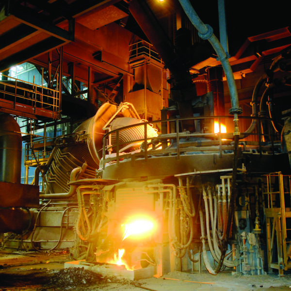
This is Part 3 of a three-part series on getting the most from raw materials, which is focused on the four interrelated factors that influence iron unit yield via the DR/EAF route:
- Ore Selection (Part 1)
- DRI physical properties (Part 2)
- DRI Handling and storage (Part 2)
- Melting practice (Part 3)
AUTHORS’ NOTE: We wish to clarify a comparison of the water absorption of CDRI and HBI, as included in TABLE I of Part 2 of this series of articles, which was published in 1Q2020 Direct From Midrex. The comparison is of the two forms of DRI when they are saturated with water to show a “worst case” condition during handling, storing, and shipping. The comparison was made to show that denser, compacted HBI is less prone to water absorption than the porous pellet form of CDRI; therefore, less reactive and safer to ship. The condition shown in the comparison is not representative of the two forms of DRI under normal handling, storing, and shipping conditions. The percentages should be considered as maximum.
INTRODUCTION
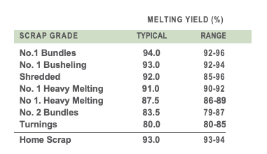
TABLE I. Typical melting yield of various scrap grades
Melting yield – the amount of liquid steel that can be produced from one ton of ferrous charge material – is one of the key considerations of EAF steel producers. It usually follows that the higher the melting yield, the greater the value ascribed to the material. The yield of ferrous scrap can vary considerably depending on its grade and the contaminants it includes. For example, low density scrap tends to oxidize rapidly, which results in a low melting yield. Scrap containing glass, plastic, rubber, concrete, wood, dirt, oil, rust, and coatings will yield less when melted than clean, well- segregated scrap. Typical melting yield reported for various scrap grades are shown in TABLE I.
Like scrap, all DRI is not the same. The melting yield of DRI can vary depending on the iron ore chemistry, metallic iron content, carbon content, and melting practice. As we discussed in Part 1 of this series, the objective when selecting iron ores for direct reduction is to use those having high iron content, low gangue content (especially SiO2 and Al2O3), and good reducibility characteristics. Metallic iron content of the DRI will depend on the degree of reduction achieved in the reduction process – the higher, the better. Carbon in the DRI should be sufficient to reduce any residual iron oxide and to carburize the bath and support oxygen injection.
Yield losses due to material handling and storage result from breakage, spillage, dusting, and rusting and are relatively straightforward, as we discussed in Part 2. Low yield during melting is harder to understand, but it can be the largest single source of iron loss from ore to liquid metal in a DRI-based steelmaking operation.
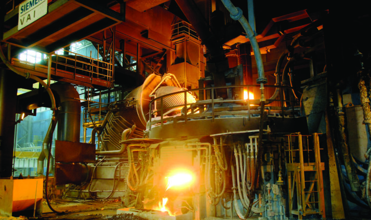
PART 3 – MELTING PRACTICE
DRI is mainly used in EAF steelmaking. Scrap/DRI feeding ratios typically vary from 70/30 to 10/90, depending on the steel being produced, the melting practice, and the availability of scrap. In scrap-deficient regions, such as MENA, the feed can be as much as 90% DRI. CDRI and HBI are batch charged along with scrap in a clam shell-type bucket, and CDRI and HDRI are continuously fed during melting. DRI usually is charged in a way to assure it is positioned as close as possible to the center of the EAF to reduce the tendency to oxidize and cluster, which can result in high iron losses, delays in operation, and unexpected damage to refractory materials.
When continuously charging DRI, the feeding rate should be such that the steel bath is maintained at a constant temperature. If the feeding rate is too low, the bath temperature will increase and the melt will tend to “outrun” its schedule and/or have less iron units than required. If the feeding rate is too high, there is a risk of forming “icebergs”; the slag temperature is decreased, creating a thick crust, which the DRI, especially in pellet and lump form, cannot penetrate. [1]
There are four potential sources of iron unit loss during melting:
- exhaust of the EAF
- metallic iron lost in slag
- oxidation of iron to the slag (carbon deficiency)
- oxidation of iron to the slag (EAF operation)
Dust losses to the EAF exhaust system
Dust losses to the exhaust system are very dependent on furnace operation, location and control of the off-gas collection, method of adding DRI, and dust content of DRI material. This can exceed 2% of the charged material in some cases.
Metal droplet losses from the furnace during de-slagging
Metal losses during de-slagging are very dependent on the timing of DRI additions and the de-slagging operation, as well as the total volume of slag that is being generated. When very large slag volumes are generated, metal droplet retention time in the slag can be longer and the residence time of the slag in the furnace can be shorter, leading to significant losses.
Iron oxide loss to the slag when the DRI is carbon deficient
The third source of iron loss during melting of DRI/HBI is rarer than the first two. It can happen when the DRI has a low carbon content and low metallization (higher amounts of unreduced iron present as FeO in the DRI). Under this scenario, oxygen from lances will react with iron as carbon is depleted, causing the iron to oxidize. This occurs because there is not sufficient carbon to protect and reduce the FeO in the DRI. Typically, DRI producers of both captive and merchant material will have a product chemistry target that has a surplus of carbon relative to the retained iron oxide in the material.
Iron oxidation to the slag driven by furnace thermodynamics and kinetics
The fourth source of iron loss during melting of DRI/HBI in a steelmaking furnace is more difficult to understand. Acidic gangue (SiO2 and Al2O3) from the iron ore pellets is not affected by the direct reduction process and enters the EAF in the DRI. To maintain slag basicity, basic slag conditioners (like CaO) are added to the vessel, resulting in larger slag volume. If the percentage of FeO in the slag is maintained constant, then more iron weight is lost to the slag.
Consider a simple case of melting 100 kg of DRI containing 3% SiO2. This initially will produce 97 kg of liquid iron and 3 kg of SiO2. To balance the V ratio* at 2.0 requires the addition of 6 kg of CaO and 2 kg of MgO to protect the refractories. The CaO+MgO+SiO2+Al2O3 represents approximately 65% of total slag make up, thus the total slag weight is approximately 17 kg. With 30% FeO in slag, that represents 5 kg of FeO or 3.9 kg of Fe lost to slag (3.9% yield loss on iron units). The 30% FeO volume comes from the balance between carbon in the steel, dissolved oxygen in the steel, and FeO in the slag. This balance is driven by thermodynamics and the stirring conditions in the furnace (kinetics), as shown in Figure 1, which was generated using actual plant data.
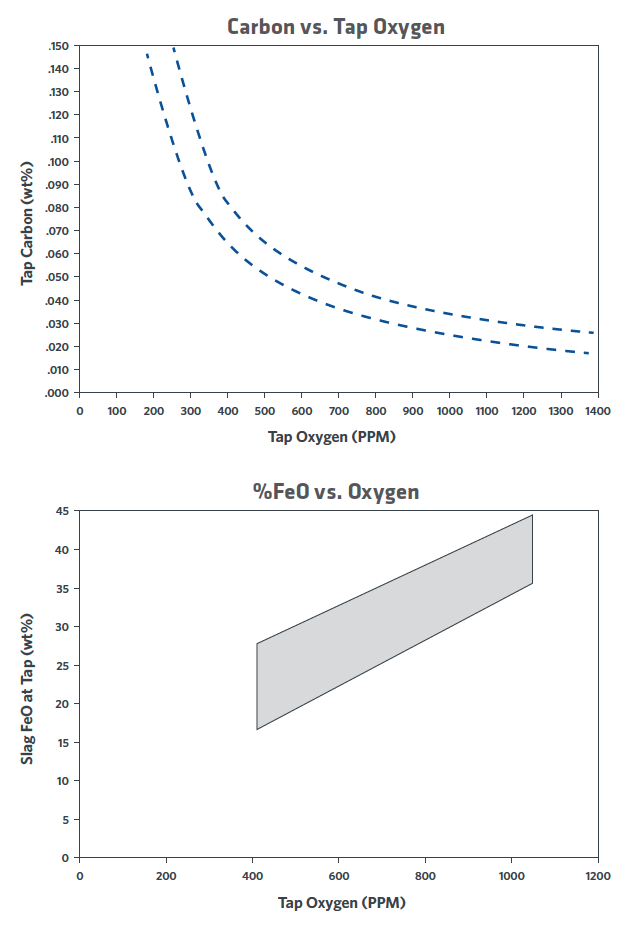
FIGURE 1. Relationship between tap carbon, dissolved oxygen, and slag FeO
Higher slag volumes or higher FeO content of the slag will lead to higher iron in the slag. This is not unreduced oxide from the DRI product and is completely independent of metallization and DRI carbon content. This is the equilibrium (or dis- equilibrium) of the slag with the oxidation state of the liquid steel being produced. The EAF is a relatively poorly stirred vessel, as compared with a BOF or QBOP/OBM. Efforts to improve stirring in the EAF will improve the oxygen/carbon/ FeO balance in the furnace and reduce the penalty for higher gangue DRI, as shown in Figure 2.
Melting practice can help mitigate iron losses to the slag. Iron can be recovered by using injection carbon; however, this can be expensive and often yields inconsistent results. Another option is to melt in with low FeO (high carbon) and slag off prior to deep decarburization. This can be difficult to achieve in actual practice in a high productivity shop. Most often, melting, decarburization, and feeding of DRI occur simultaneously.
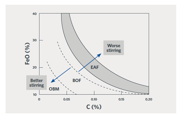
FIGURE 2.
Relationship between % FeO in the slag and % C in the steel at tap. [1]
Careful slag chemistry control also can help minimize iron losses to the slag. Slag basicity has a strong impact on activity of FeO in the slag. By targeting the correct slag basicity, an equivalent oxygen activity in the slag can be achieved at lower concentration of FeO in the slag.
As Figure 3 shows, pushing the V ratio from 2.5 down to 1.8, can double the ‘potency’ of the FeO in the slag. In theory, an 18% FeO slag at V = 1.8 has the same oxidizing potential as a 36% FeO at V = 2.5.
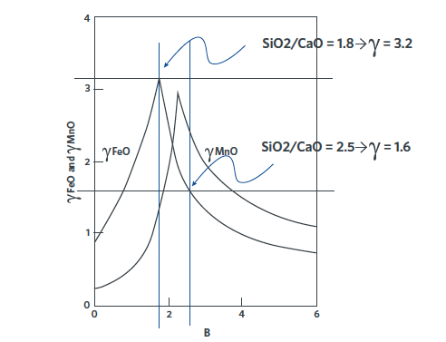
FIGURE 3. Effect of slag basicity on the activity of FeO. [2]
From the previous example, let’s consider that the slag must be modified to perform de-phosphorization. Instead of V ratio = 2 and FeO = 30, consider V ratio = 2.8 and FeO = 35. The total slag weight is 3 kg SiO2 (from DRI) + 8.4 kg CaO (for V ratio of 2.8) + 2 kg MgO (for refractory) / 0.6 (SiO2+CaO+MgO represent ~60% of the slag make up) = 22.3 kg/DRI ton of total slag. With 35% FeO in the slag, this means 7.8 kg of FeO or 6.1 kg of Fe lost to the slag. (Note: In this example, a relatively small change to accommodate phosphorus removal increased iron loss from 3.9% to 6.1%.)
SERIES SUMMARY
Overall iron unit yield from ore to liquid metal can vary over a wide range via the direct reduction/EAF steelmaking route. Iron unit loss can add up to greater than 15% quite easily. The major root causes of these losses include:
- • Iron ore physical properties, which affect breakage during handling of the oxide
- Handling losses if DRI / HBI breaks into chips and fines; although much less prominent in HBI. Handling losses can be controlled by careful design and selection of material handling equipment and recovery/recycling of dust and fines that are generated.
- Spillage
- Weathering during storage
- Losses resulting from melting in with a large slag volume. Losses to the slag during melting really start with the iron ore chemical properties.
Melting practice also plays a role and understanding the chemistry of slag generation in a steelmaking furnace is important. The large costs associated with iron unit loss are sometimes hidden, as they are distributed across several unit operations. These costs must be controlled in a competitive iron and steel market. Careful consideration at all steps highlighted in this series of articles can lead to significant improvement in yield, and thus a major reduction in operating cost.
*V ratio is defined as % CaO / % SiO2 in weight percentage – also called B ratio or B2 ratio.
Related Reading
 Mar 21, 2024